[Solved] ADC_battery example

Hi,

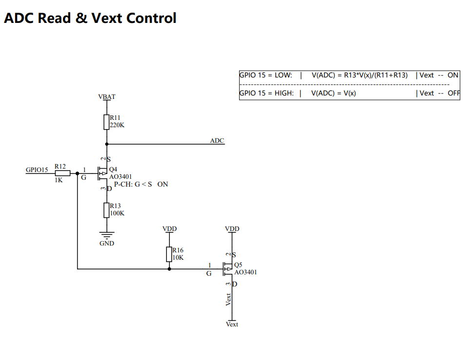
Unfortunately the ADC example and the ADC_battery example both measure the same values (the voltage applied externally to the ADC) only that the later multiplies it by 2. Setting ADC_CTL to low has no effect and does not mesure the voltage of the attached battery (at least not when the USB power is connected and the Serial out put is visible). Am I missing something? Some wiring needed to make ADC_CTL work?

Background: I have 2 cubecell boards I want to use for solar monitoring and temperature of water in my pool. For the first use case I want to use the ADC to measure the open circuit voltage of a small panel (1V rating). But it would also be good to measure the battery voltage of the lipo battery I want to use. I’m not planning to use a solar panel as the lipo battery should last for long enough.

Regards, Marcus from Heidelberg

Hi @marcus


did you try this example? You can try this example with a USB cable connection, with USB connected, the value should close to 4.2V

The ADC example is to display the pin voltage, and the ADC_battery example is to display the battery voltage. When the battery voltage is measured, there is a voltage division in the circuit, so the pin voltage needs to be multiplied by 2 to get the battery voltage.
ADC_CTL can be pulled low directly using digitalWrite (ADC_CTL, LOW).

Yes, that’s the example I’m using. When I use it the voltage is not 4.2V on USB power but its 1.5V which is double the voltage on the ADC pin. When I use the ADC example then I get .75V which is the voltage on the ADC pin.

Maybe you can directly test the voltage of the ADC pin with a multimeter, it should be around 2V.

Yes, I have tested with a voltmeter and the ADC pin always has 0.75V as its tied to a voltage I want to measure. What is not working is the ADC_battery example where pulling ADC_CTL to low does not have the desired effect - the voltage measured is 1.5V which is not the 4.2V which I would expect when powered by USB.

I checked with a second cubecell that does not have anything tied to the ADC pin. In this case the ADC_battery example works!

I was expecting that one could measure the battery voltage with ADC_CTL low and another analog value with ADC_CTL high - this way one could measure an analog sensor value and also check on the battery voltage of the node in an IoT scenario. Too bad that this does not seem to be possible.

Workaround: Attach a voltage divider between VIN and GND and put the in between level on a GPIO pin that you make an INPUT. This way when you get close to your desired cutoff voltage for safe operation (from then on the device should only sleep) the GPIO input goes from 1 (above threshold) to 0 below threshold. Or you attach another ACD converter, or you use a digital sensor.

Why ADC does not measure voltage below approx 3,4V ?
Can I change it?
If battery volate is approx 3,3V 3,2V, ADC pin show stil 3,4 V
It is possible?

Bonmis

Hi, we found a bug in the source code of Vref setting, we had fixed that bug since last commit.

Install the development framework via git.

Thank You, now works fine :slight_smile:

Bonmis

So also for me it does not work to measure battery voltage and some external voltage. Once external voltage is connected the battery voltage cannot be measured anymore. So the ADC pin needs to be floating in order to be able to measure battery voltage. Is this correct?

I don’t think so…

They should work together.

I am just asking for clarification! So you can read the battery voltage with uint16_t voltage = getBatteryVoltage();` and then also analog read something else on pin 2 ADC? If so how would I do that?

No, the ADC pin in CubeCell 6501 is connected to VBAT and controlled by GPIO 7 all the time (Indeed the AO7801 is a two MOS-FET combination). GPIO 7 control Vext and ADC input at the same time.

Analysis in principle from the circuite diagrame, if set the GPIO 7 to HIGH, the ADC can read other analog source. But disable the GPIO 7 will disable the Vext at the same time.

#include "Arduino.h"

#include “LoRaWan_APP.h”

void setup() {
// put your setup code here, to run once:
Serial.begin(115200);
}

uint16_t voltage;

void loop() {
// put your main code here, to run repeatedly:
readBat();
readADCPin();
}

void readBat(){
uint16_t voltage = getBatteryVoltage();
Serial.println(voltage);
delay(1000);
}

void readADCPin(){
voltage=analogRead(ADC);//return the voltage in mV, max value can be read is 2400mV
Serial.print(millis());
Serial.print(" ");
Serial.println(voltage);
delay(1000);
}

This looks as if it does read both! I still need to do some more testing but it reads both the LIPO battery and a 1.5v battery on ADC.

Hello, so there is no way to use same ADC pin for battery and external source? Like the pin has to be floating when measuring the battery?

I needed the same setup, that is, measure the battery voltage every 15 minutes, then measure a sensor with it’s own source every minute.

I’m trying to make it really low power so I don’t want to opt for adding more components.

For the ASR6501 series itself, it hard to do that, because the ASR6501 only have one ADC channel, if you can add an external analog switch, that maybe solve your problem.

Do you consider use the ASR6502 series? The 6502 have three ADC input channels.

I got it to work by adding a switch to dis-connect the one while I read the second! I still had to adjust the code, but it can be done!

Hi,

I have a similar issue with the CubeCell module where the ADC reading for my battery voltage will not go below 3600.

#include "Arduino.h"
#include "LoRaWan_APP.h"

#define Vext GPIO6

void setup() {
  // put your setup code here, to run once:
  Serial.begin(115200);
  pinMode(Vext, OUTPUT);
  digitalWrite(Vext, LOW);
}

void loop() {
  
  int ADCvoltage = analogRead(ADC);
  int BattV =0;
  
  BattV = ADCvoltage*(220000+100000)/100000;
  
  Serial.println(BattV);
  
  delay(1000);
}

I have used the recommended schematic and can confirm the ADC reading works for battery voltages above 3.6V

I have done a git pull request to update to the latest framework, but still no luck.

I think you can measure the ADC pin voltage and check the RAW value first.
And I think you using a Voltage divider 220k on the high side and 100k on the low side.
the equation of BattV should be BattV = ADCvoltage*100000/(220000+100000);

Also, please check the voltage on GPIO15. It should be 0V to turn on Q4.

Thank you @ksckung for your response, yes I have used that exact schematic except I have used GPIO6 instead of GPIO15.

I tried your equation, however, I have checked and I think my math is correct.

The issue is the raw ADC reading does not go below ~1100 even if the actual battery voltage is like 2.9V