[Solved] ADC_battery example

Sorry, your equation is correct.

I check with the ADC example in Cubecell library.
When I apply 1V to the ADC pin, the RAW output is 1003.
When I apply 2.1V to the ADC pin, the RAW output is 2109.
It seems it is converted to mV in heltec ADC library.

In HeltecTM CubeCellTM Series Frequently Asked Questions, It noted ADC input voltage can NOT higher than 2.4V. Please check your ADC pin input voltage within range or not.
https://heltec-automation-docs.readthedocs.io/en/latest/cubecell/frequently_asked_questions.html

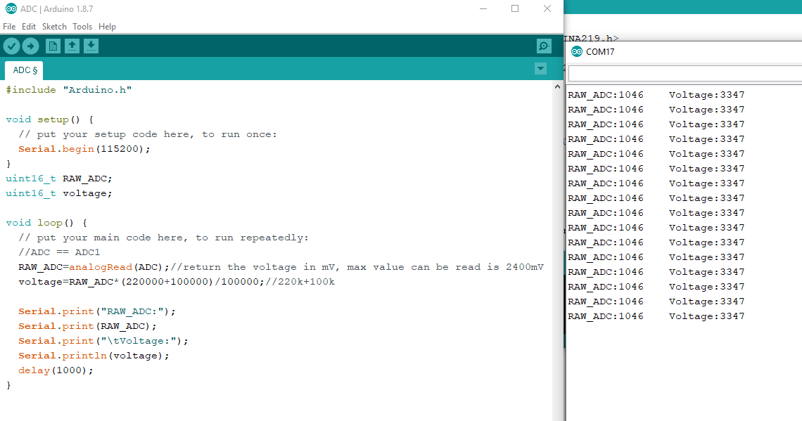
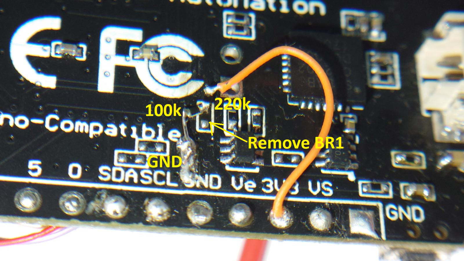
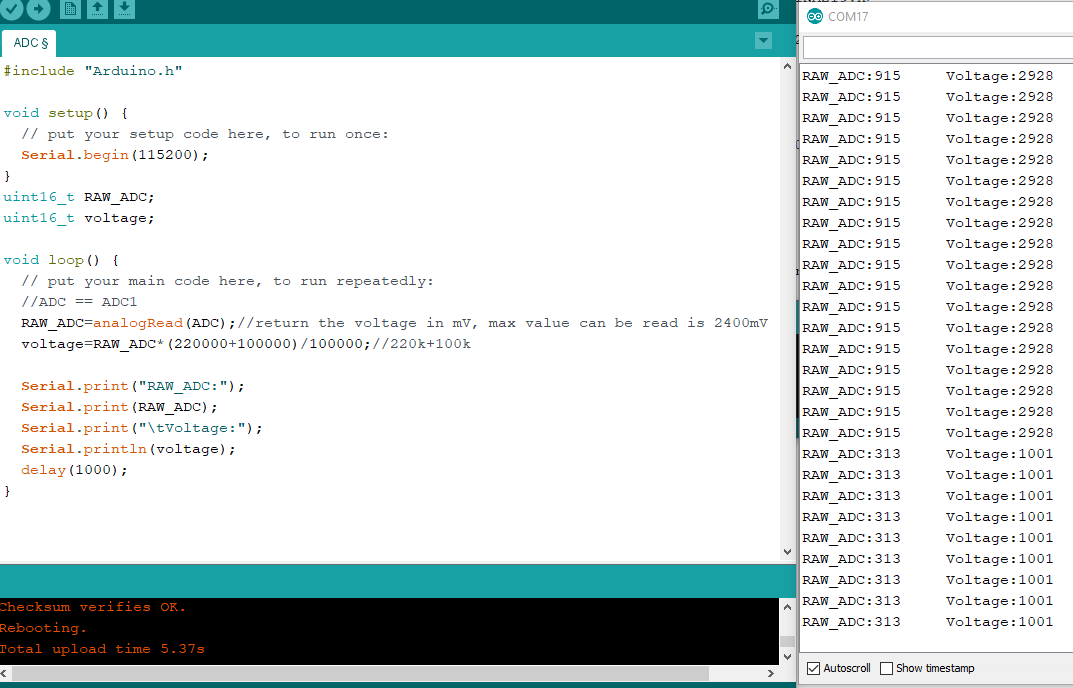
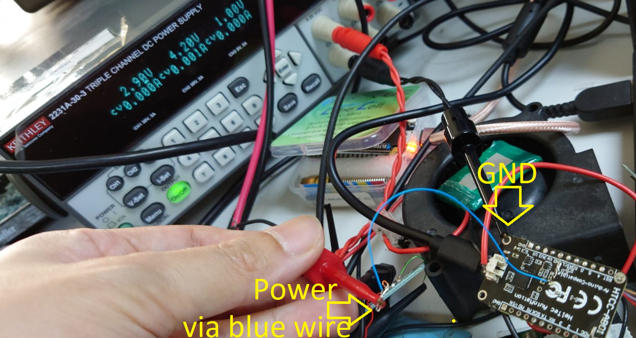
If your setup is correct,when you connect 2.9V battery and add voltage divider(220k +100k). The voltage on ADC pin should be 2.9*100000/(220000+100000)= 0.90625V, the RAW value should be around 906.

#include “Arduino.h”

void setup() {
// put your setup code here, to run once:
Serial.begin(115200);
}

uint16_t voltage;

void loop() {
// put your main code here, to run repeatedly:

//ADC == ADC1
voltage=analogRead(ADC);//return the voltage in mV, max value can be read is 2400mV
Serial.print(millis());
Serial.print(" ");
Serial.println(voltage);
delay(1000);
}

One more thing. If you connect the battery externally, please remember to remove the 0ohm jumper (BR0) of the internal voltage divider.

Hi @ksckung,

Thank you for your reply. Like noted we are using the recommended schematic with the voltage divider circuitry.

Again just to reiterate the issue is that the ADC raw reading does not go below ~1100mV. I will double-check all the raw readings from 700mV - 2300mV to confirm exactly what raw range we are getting. From the previous testing though the ADC raw value will not go below ~1000mV-1100mV.

Try for yourself maybe, if you make the voltage divider(220k +100k) on the raw ADC pin, remove 0ohm jumper (BR0) and then hook up a power supply simulating a battery voltage of 3.3V. What is the raw ADC value that you get, and then when you do the math does that equate to 3.3V?

Digital multimeter reading:
3.3v: 3.297V
ADC pin: 1.037V

Software:

Hardware:

Apply 2.9V and 1V using power supply, also get correct reading.

I use two Cubecell boards HTCC-AB01 withe the examples Skech “LoRaWAN_BMP280.ino”
When I connect a lipo battery with 4.18V, I get through the serial monitor arduino a value of 4202 . Does the library convert that to mV?
Another question:
In my Cubecell Board block diagram there are no 220k and 100k voltage dividers between Vbat and ADC.
(these are only available on the Board WiFi_Lora 32 (V2.1)
just a voltage divider with 2 x 10 kOhm. Is there for the Cubecell
different versions?
Can someone help me?

yes, the anwser is YES.

Actually I tried also HTCC-AB02, I am having the same problem, I used a sensor with it’s own external source on one ADC pin and tried measuring the battery, if the sensor is connected I am getting reading of 44mv and when it is not connected I am getting somewhat accurate readings of the battery. I was trying to minimize as much as possible power consumption so opting for adding components is last on my list. Please help.

Do you mean that ADC is not accurate after AB02 is connected to the sensor? What sensor are you using? How is the connection between AB02 and the sensor?

My sensor generates its own power, it is two wired so i simply connected vcc to adc pin and while the other is on ground.

My code goes this way: i am reading battery every 30 minutes, while reading adc pin every second. Now if i am not reading sensor, specifically calling analogRead(adc), battery seems to give correct voltage. But when I do I am getting wrong values both voltage and the next sensor reading.

I think the problem may be: Your sensor does not use the same power supply as the MCU.

Maybe you can try to initialize the sensor every time before reading data.

Hi, now its fine with the updated library. Even if my sensor has it’s own power supply it is not affecting anymore. Thanks guys.

1 Like