is it possible to use the only one ADC pin to read analog data from 2 different “sources”?
I need read data from photoresistor to check the light level outside and also I need to read battery voltage.
I’ve read a lot of threads here and still not sure if I understand everything correct.
The most information about ADC reading here - [Solved] ADC_battery example
Seems in this setup it would be possible to read analog signal from ADC pin and also possible to read battery voltage from battery connected to Vbat JST connector.
Is it correct?
If so - it means that you can use only LiPo battery.
But there is another issue - AB-01 boards powered from LiPo via JST connector has a big power consumption in sleep mode - for example all my boards consumes about 42uA - there are several thread about it here.
Fully charged LiPo has 4.25v and somehow this fact leads to big power consumption during sleep mode and it will begin to decrease only when the voltage drops to <4v which would mean that LiPo battery is almost dead.
The only way - is to use Vdd pin for power the board - in this case its possible receive about 10uA of power consumption.
But you will need to use, for example, LiFePo4 battery, because Vdd pin allows only 3.3v.
So in this case becomes interesting - how to check the voltage of such LiFePo4 battery connected to Vdd while having the ability to read a second analog signal, for example, from a photoresistor.
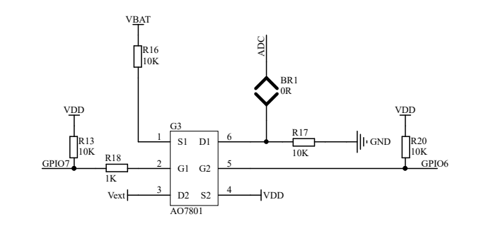
This may be a lost in translation issue as the docs are not super explicit, but as a native speaker of Geek & PureBS, it’s clear to me, you’ve one input pin, if you want to free it up from reading the battery voltage you remove BR1 and then you can use it as you want, but then it’s no longer connected to the battery.
It does not even slightly imply that removing it allows you to do both nor does the schematic.
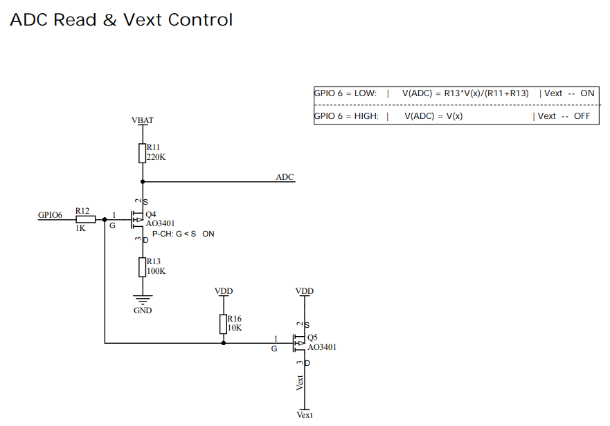
There is no circuit that would allow you to have the battery voltage and an LDR on the same pin without additional switching, an example of which is the Vext circuit further down the page.
You could buy an I2C based light sensor.
But you seem to have so many issues with the AB-01 that you may want to consider a new post with bullet points of what you want to do and we can recommend something that will be less of a struggle.
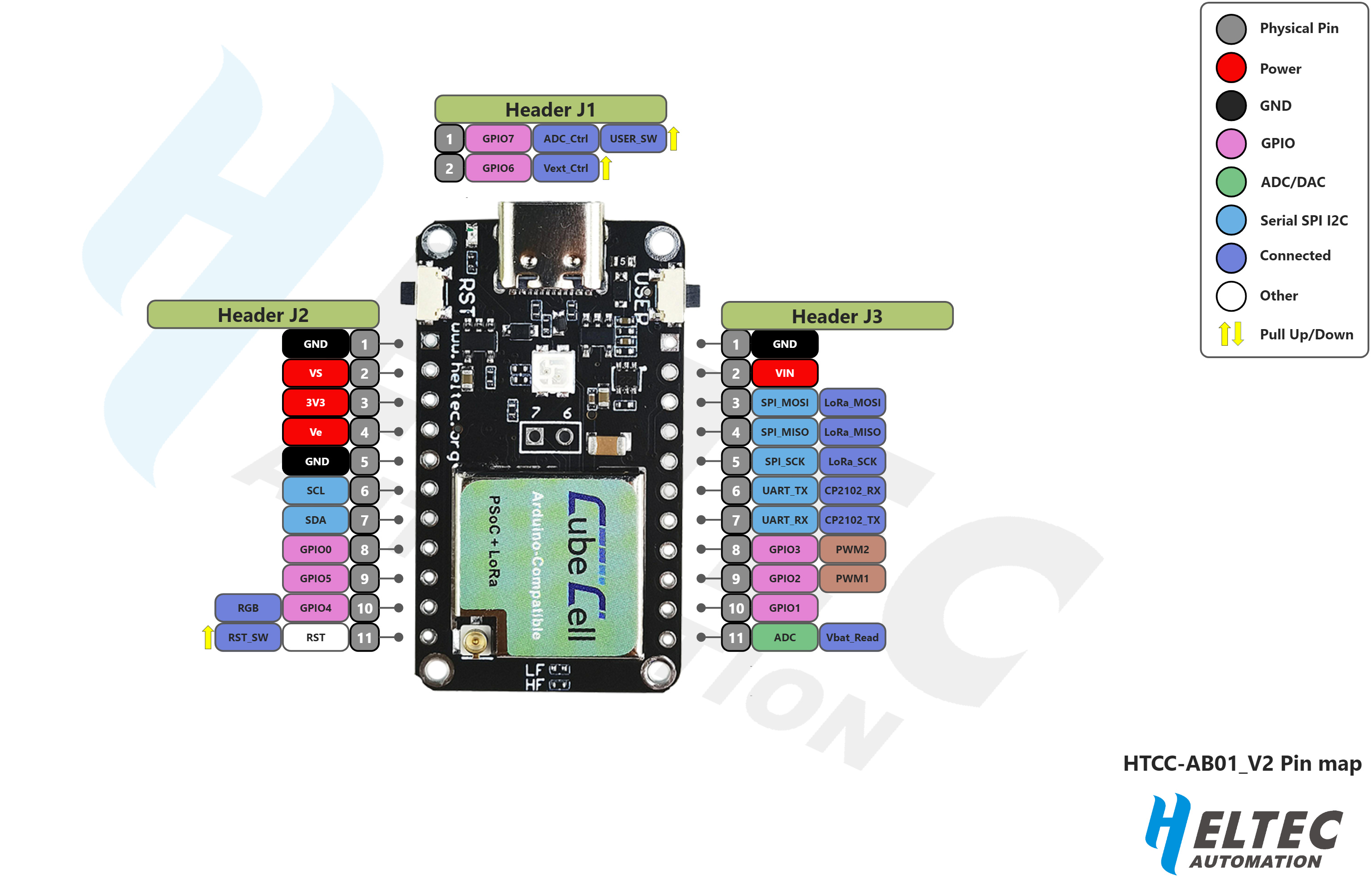
Remember that that the V2 boards now use the ASR6502 processor, which has three ADC ‘ports’. Unfortunately, Heltec only provides access to two of them (all three are available on the Plus board) and one of these is dedicated to reading the battery [connected through the JST connector] voltage. So the ADC pin that is broken out on the board is no longer required to read the battery voltage and can be used for any other purpose—i.e. you can read both the battery voltage [supplied through the JST connector] and an analog value from a device connected through the ADC pin without needing to change any hardware.
The second case you describe, however, is not using the ‘dedicated’ battery ADC, so you are left with a single ADC pin. I have used a 74HC4051 analog multiplexor in other applications, so that may be an option if you really need to use the CubeCell Dev-Board but, as @nmcc suggests, it might be getting close to the time when it would be worth considering a different platform.
Having said that, I have several applications based on CubeCell boards. Most are battery powered, through the JST connector but with solar recharging, so the battery never runs flat. I do, however, have a couple of very simple, battery-only BME280 configurations, with both V1 and V2 CubeCell boards. They are little more than trivial thermometers but, while I’ve never worried about the battery life (they are easy to access and no problem to change the battery periodically), they run most of their [900mAh Li-Ion] battery life (worst case ~6 weeks, when reporting battery voltage and temperature [via LoRa] every 60 sec.) with a reported battery voltage of less than 4V. So if LiPo battery voltage is a problem, you could consider using a suitably sized Li-Ion battery.
Thank you all for answers!
Sure, my English is not perfect and my experience in microcontrollers stuff as well not good.
But Im keep learning and most of my knowledge comes from answers in similar threads.
And above correct only for V2 boards, right?
And if I modify V2 board by info from FAQ - remove resistor - I will receive 2 ADC pins and can measure two “sources” like photoresistor and LiFePo4 (via external voltage divider), right?
And If I still want to continue use my V1.2 boards which based on ASR6501 - I would have only 2 choices - use default board configuration only for battery voltage measuring via JST connector.
Or, after removing resistor as stated in FAQ - use ADC pin for external photoresistor measuring.
But also in this case it seem possible to use some analog multiplexor module to use this only one ADC pin for measuring two “sources”? I would need to check this variant also…
So this is the my main goal - check if I can use my AB-01 V1.2 which I already have certain amount of which doesnt allow me just simple switch to another board type)
But unfortunately, seems I need switch to AB-01 V2 or even AB-02 which would be more suitable.
As for batteries type - If I use AB-01 V2 or AB-02 with Li-Ion which is nominal 3.7V and power the board from standard JST connector - can this Li-Ion battery be charged from onboard charger and can I use default way to measure voltage via dedicated ADC pin?
If it will work without modification V2 board - I will consider to use Li-Ion…
The only concern in this case - Im not sure how Li-Ion battery will work in cold conditions. My current LiPo batteries located inside a snow pack where about 0 C degree almost all time and this allows them to be charged a bit from solar panel which installed on top of the device -under snow of course.
LiFePo4 also knows as good for low temperatures so I going check it also - but I cant connect it to JST and charge from onboard charger. so I need to choose the best variant.
No, there’s only one ADC pin—labelled ADC in the schematic—that’s actually broken out on the board. The processor pin—ADC1 in the schematic—that’s used to read the battery voltage is only used internally.
Correct
You’ll need the AB-01 V2, at least, if you want to read the battery voltage and read another external analog value without using something like an analog mux. The AB-02, which I have used when I need support for two external analog inputs, will give you access to two ADC pins.
In my AB-02 applications, I use a Li-Ion battery that provides a usable voltage in the range ~2.7–4.2V—my battery-only CubeCell nodes only die when the voltage drops below ~2.7V. The onboard circuitry will charge, using voltage supplied on the VS or Vin pins or the USB connector (I have used all three sources in various applications), any [appropriate] battery connected through the JST connector. And yes, in my experience, the internal battery voltage measurement circuitry will measure the voltage of any source that is connected through the JST connector.
I know it’s not recommended, so I don’t know how the life of the battery might be impacted because the LiFePO4 charging requirements are a little different, but I have used a LiFePO4 battery connected through the JST connector, although only in a test environment on the original V1 boards using solar panel charging. I didn’t continue with that option primarily because the Li-Ion option was much simpler and it worked just fine in my environment.
Pretty much all of my testing of configurations has been purely empirical—I just hook things up and see how they work, without worrying too much about how any calculations suggest they might work in practice. This is, for example, how I worked out the size of the solar panel I needed—I just kept connecting up smaller panels until they stopped working, then used the smallest one that did work. Initially, concerned about battery life, I also measured sleep current usage but when I discovered that my solar panel would fully recharge the battery every day, even in overcast conditions, I stopped worrying about that. I was also a little surprised to discover that, even after the clear plastic covers on my enclosures had deteriorated badly—they yellowed and were no longer visibly transparent—after several years in the sunlight, the solar panels [inside the enclosure] still catch enough energy to recharge the battery each day in just a couple of hours. The very infrequent, light snow falls this I get in my environment never last for more than 24 hours, so I’ve no idea how much snow on an enclosure or panel would impact its performance—I have more trouble with processors failing when the enclosure temperature rises above 50°C… (Just for the record, they come good again as soon as the enclosure drops back below ~50°C, so the high temperatures—I don’t actually know how hot they get, because the node stops transmitting data!—don’t seem to be destructive.)
Thank you for detailed answers!
I have way more worser conditions - winter in mountains, so I cant fully rely on solar panels.
Also I cant change batteries during working cycle - from October till May…
So I need stable power sybsystem - a lot of mAh battery (or batteries connected in parallel to increase capacity), good power consumption in sleep mode and way to little charge battery sometime when it is possible by weather conditions.
Because of all of this am looking for the best variant to use type of board, type of battery, sleep mode, circuit for measure and charge battery…
Anyway - if it possible to charge Li-Ion batteries connected to JST connector - I will check this type of batteries also even there is still maybe the issue with big power consumption in sleep mode -so far I have 31uA for AB-01 V2 with LiPo 4v - which is very big as for me…
only one question regarding this:
so why we have this modification in the [FAQ] for HTCC-AB01_V2 version?
for me it seems if this would be done for V2 board - it will also can use internal dedicated ACD for external “source”. but there is a question - where is this second ADC pin? )
if so - then I can safely power AB-01 V2 via Vdd from LiFePo4 battery and use this “mystery” second ADC pin + voltage divider to measure voltage on battery…
Am I wrong?
After a fashion mountains have it good, little chance of mist & fog.
If this really needs to deliver and it regularly gets colder than 0℃ then you will find that the LiPo & Li-Lon batteries aren’t great at charging and will start to show signs of poor power delivery from around -20℃ onwards.
As, despite hints, we are still somewhat clueless as to what you are trying to achieve, it’s hard to know how important this is. If you need to be sure of getting some messages if only a reduced count, then you should use Lithium (non-rechargeable) batteries as backup - they cope well down to -50℃.
Or insulate the box very very well (expanded polystyrene helps) and perhaps a big 10W resistor as an auxiliary heater for when the sun shines - but turn it off by approx +40℃ before you go too far the other way!
thank you for your message!
yes, it really needs)
but with all due respect, unfortunately the reality in the mountains is somewhat different than you imagine)
but Im really dont understand - Is it really possible to get an answer to a question only if the question seems really important?
anyway - seems so far I have all information - I will switch to AB-01 V2.
I just curious about that info about modification of V2 in FAQ - why one would need to remove that resistor on V2?
Given that I have a battery-powered CubeCell Dev-Board V2, transmitting every 60 sec, that will run for ~6 weeks on a 900mAh Li-Ion battery, a simplistic calculation might suggest that the same configuration could run for as long as 60 weeks if it were transmitting only once every 10 minutes, given that the most significant current draw in any cycle is the ~50mA drawn when the radio is transmitting. Of course, that’s not a very sophisticated analysis, and I understand that it may not be very practical in your case to just give it a go and see what happens, but we can all overthink things at times.
I guess I can make two observations here. The first is the title of that section in the FAQ:
How to use the ADC pin for AnalogRead (ASR6501)
Note the explicit reference to the processor in question—ASR6501, not ASR650x as appears in other parts of the documentation when making more general references.
Which leads to the second observation, being that, unfortunately, the Heltec documentation can be found a little wanting at times—failing to point out critical changes when board upgrades are released, and failing to update documentation accurately.
Most likely, the V2 update of that part of the FAQ was just not well-considered. Someone, charged with updating documentation with the release of the V2 board, but with no real knowledge of how the board actually worked—yes, there are people in organisations responsible for the preparation of documentation who have little working knowledge of the product they are documenting—simply added the V2 board without understanding the original purpose of the FAQ, that being to ‘release’ the single ADC port on the ASR6501 processor from it’s default configuration to allow the ADC pin on the board to be used.
Modifying a V2 board as suggested may well also release the relevant processor ADC port from its default configuration, but because there is no alternate connection to an external pin on the V2 board, it will just be left ‘flapping in the breeze’, as it were…
laser ~150mA with short peak to 300mA during max 5 sec.
usually device works 2 times per day: 60 sec of sleep mode, then wakeup for RX LoRa for 600ms - if no requests - sleep again for 60 sec. if there is request - check sensors, send data, sleep again.
sometimes it needs more than 2 TX session per day.
2-3 LiPo 4500mAh from aliexpress connected in parallel works from mid October till beginning of May.
OK, I understand better now, I just hadn’t gone back that far in time!
We are volunteers so there is an element of answering just the low hanging fruit and/or ending up rather snowblind in the blizzard of discussions & questions.
Which questions are outstanding? Bullet points would help clarify.
but wait - above in this thread we are already decided that AB-01 V2 board already have ADC pin on J3 (very bottom right green ADC icon) header which can be used for external “sources” measurements.
and as well V2 board has dedicated internal ADC for measurement battery connected to JST.
so why it needs to remove resistor to use J3 pin 11 for ADC analog read??
Im confused…
The schematic shows three ADC pins top left of the MCU. ADC1 doesn’t appear to go anywhere. ADC is connected to the circuit bottom right which connects it to the battery and this same ADC is broken out on the header.
I have two v1’s but no v2 so I can’t check what’s what with an actual board.
Re-reading the above I’d have to surmise that @UniquePete doesn’t have a V2 board either so can’t check the connections given the phrases he’s used of “may well also release” and “flapping in the breeze”. Maybe he can confirm his wording.
If you have a multimeter and can tell us what the resistance is between the edge pin and the resistor on the back that the docs say to remove, that would give us more info. However I’m not sure why they’d have a resistor to remove to give access to the ADC used by the battery if they give you a pin on the edge connector.
I do have both V1 and two ‘variants’ of V2 boards (although it’s not obvious that there’s any difference between the two other than the label on the shield—the first batch I received had blue-green labels, like in the HTCC-AB01_V2 Pin map above, and on the next batch they were etched), but I made the same observation that you (@nmcc) did with regard to the inconsistencies in the schematic. I couldn’t see why they would bother with any removable resistor, if indeed there really was one [that could be removed, in a practical sense], if that was only going to disable the battery voltage reading circuit. Hence the use of the word “may”, because it wasn’t obvious to me that that was what would happen if the resistor identified in the FAQ was removed… Which then led to my comments/conclusions in relation to the documentation, which were also ‘coloured’ by prior experience with the Heltec CubeCell documentation…
It is a hot-mess. If I had a board to hand it would take me moments to remove the resistor to probe the board and can easily put it back. But I don’t and I’d probably only be motivated to do so if I was retailing these puppies, which I guess makes for a choice for a low power LoRa board except I can’t get them for much less than £14 whilst I have a whole pile of Wio-E5 (STM32WL5J) boards of my own design for ~£8 …