Solar Panel Input on Cube Cell Board

Hi.
I can’t find information about the solar input.
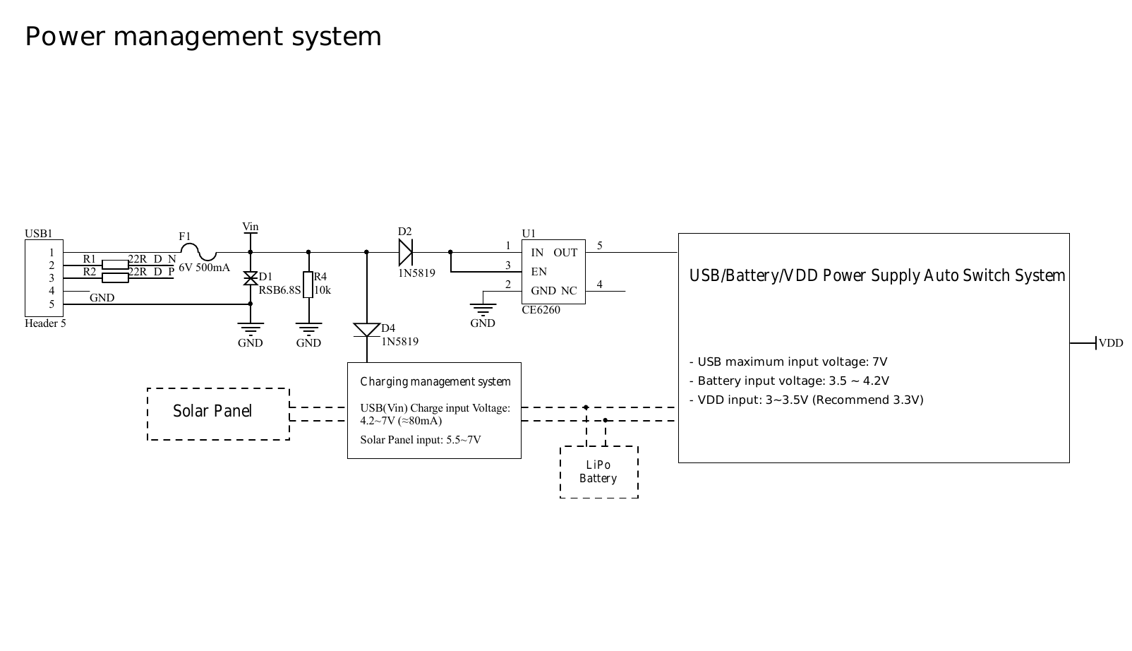
I could only find that the input is for a 5.5V or 7V panels
In the schematic PDF it is not detailed


As solar panels had no fix voltage, I would like to know:
. Max. Amp allowed
. Max Voltage allowed
. What is the voltage ‘window’ when the board will work?
. What would it happen if the voltage drops? if it goes up?
I connected a 5.5V 100mA solar panel but, as it was cloudy and it was bringing only 2.X volts, it didn’t turn the board on.
Then, I connected 7.5V panel giving ~4.5V and it start working.
But I am afraid of what would happened over 7V.
I would like to know:
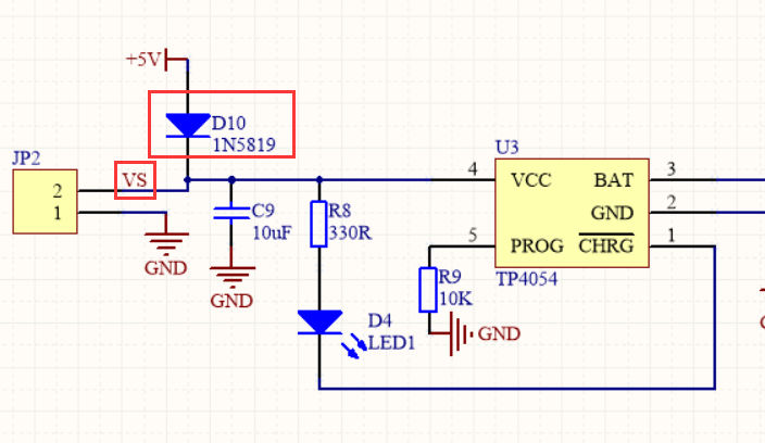
. Is the solar input charging the battery?
. It would be helpful too to know the IC power manager for this.
Thanks!
Regards,

Well, you’ve answered one of my questions at least, that being “Do you just connect the positive lead of the solar panel to the VS pin?” (I’m assuming that that’s what you did.)

But I too would like to know if the solar panel input charges the battery.

connect the solar panel
++ --> VS
– --> GND

at it will charge the battery.

if the solar panel voltage gets below 4.2V it will not charge.
the charging circuit have a maximum input of 7V.

the solar panel input is only for charging the battery. dont use it to power the cubecell.
the cubecell will reboot everytime the voltage drops below 4.2V and will reboot.

Sure. To VS input and GND.

Do you mean when the voltage drops below 4.2 and there’s no battery connected? or even with battery connected it will reboot?
Over 7V, the board will be damaged?

Yes without battery .

1 Like

Which charging IC is used? It would be interessting so find a suitable solar cell as I could not find one with only 7V solar input voltage.

Here is the block diagramm

It is easy to find a 6v solar cell on aliexpress for example.

Hi looking to the module-only documentation schematic here:
https://heltec-automation-docs.readthedocs.io/en/latest/cubecell/module/htcc-am01/index.html

we can see that the charging circuit is the TP4054 which seems to have a 10V max input.

So … regarding the DevBoard AB01 : where is the limitation on 7V solar input? do we have some protection like a zerner diode to prevent overvoltage?

somehow I cannot find the schematic to explain what is in the middle between the Vs input and the TP4054.

thanks

Hi,

Please refer the pciture.


Hi JasonXu,

so if Vs is direclty connecter to TP4054 the max voltage is 10V, correct?
where is the 7V limitation coming from on the CubeCell board?

thanks

Hi,

10V is correct.

The purpose of our recommendation not to exceed 7V is: Provide a buffer interval.

In a real environment, The light intensity of the sun may be high for a certain period of time or region (For example, at noon, or near the equator). The charging voltage of the solar panel may exceed the preset value. This may burn the development board.

1 Like

Hi !

Is there a way to monitor the charging state?
To see if solar panel is charging or not ?

Thank you

You could configure something like an INA219 or INA3221 module, or you could do what I do and just monitor the battery voltage. This is a very pragmatic approach, as I don’t really care how quickly things are charging, I just need to see that the battery stays charged. In my case the [14500 Li-Ion] battery voltage drops by 0.1V or 0.2V overnight, then you can see it quickly recharge back up to around 4.1V as soon as the sun comes out (or a little bit longer if it’s overcast). If the solar panel is not working, or is not ‘big’ enough (my CubeCell Plus configuration only needs a 5V/60Ah panel to keep a battery fully charged), you won’t see the voltage pick up when the sun is shining.

Yaou are basically right, no need to over-complicate things, we can see what’s going on by monitoring the battery voltage.
Right now I check the battery voltage like this:

uint16_t voltage = getBatteryVoltage();

It gives me a reading of 3306, meaning 3,306 V.

Checking Battery with multimeter shows 3,64 V.
And if remove the battery, the getBatteryVoltage reading gives still 3306.

So I guess I am not getting the real battery voltage in my code …

What development environment are you using? Arduino IDE, PlatformIO or something else? Either way, if you search these forums for “cubecell battery voltage” you’ll see numerous threads discussing various issues relating to reading the battery voltage. Maybe something there will help…

I am using Arduino IDE. Will google some more …

I was about to edit my previous comment to add that I use pretty much exactly the command you are using to retrieve the battery voltage, but I declare the variable first, then call getBatteryVoltage() in the main loop of the sketch. As I was typing that, it occurred to me that maybe there are things somewhere that are not initialised ‘properly’ when you simply declare your variable and initialise it with a call to getBatteryVoltage(). Maybe try declaring the variable ahead of time, and then calling getBatteryVoltage() in your setup() or loop() functions, after everything else has been initialised.

There is no VS pin on the AB02A. I have a max.6V Solar Panel I’d like to use. Where to connect ?

For what it’s worth, if you look at the schematic, it would seem that VIN would be the place to connect an external power source. But you would usually just be using a solar panel to recharge a battery, not to run the node directly, as such, and in this case I don’t see any charging circuit. Maybe also refer to the post above on the subject.