Rx Timeout @ US915 (902-928)

Buy about 30 devices just to develop and join our platform, since I have very good expectations for our customers. But this problem of signal reception sensitivity is making it very difficult to trust these equipments. @Supporter Please I request your help to be able to advance in the project.

In this case Capsule AC0X.
I have this issue in all device. I try for many days different configurations.

But always finish in the same issue. Some times run ok for some time but form one moment to other come the issue again and this make drain battery because need to transmit many times.

The device need to transmit many time to get the ACK from network. But network all times send the ACK.

Apparently the cubecell is deaf.

In my test I change this parameters but I have no improvements:
uint8_t confirmedNbTrials = 8;

/LoraWan channelsmask, default channels 0-7/
//uint16_t userChannelsMask[6]={ 0x00FF,0x0000,0x0000,0x0000,0x0000,0x0000 };

/LoraWan channelsmask, default channels 0-15 - 64 and 65/
uint16_t userChannelsMask[6]={ 0xFFFF,0x0000,0x0000,0x0000,0x0003,0x0000 };

*** ATTACH EXAMPLES OF GOOD COMMUNICATION AND BAD COMMUNICATION ***

Fail examples, need to re transmit many times to get one ACK.


FAIL_APP_TTN


FAIL_SERIAL

Example of good communication:
OK_serial


HERE IS THE CODE

#include “LoRaWan_APP.h”
#include “Arduino.h”
#include <Wire.h>
#include “HDC1080.h”
#include “LoRaWan_APP.h”
#include “Arduino.h”

/* OTAA para*/
uint8_t devEui[] = XXXXXXXXXXXXXXXXX; //CHANGE
uint8_t appKey[] = XXXXXXXXXXXXXXXXX; //CHANGE
uint8_t appEui[] = XXXXXXXXXXXXXXXXX; //CHANGE

/* ABP para*/
uint8_t nwkSKey[] = { 0x15, 0xb1, 0xd0, 0xef, 0xa4, 0x63, 0xdf, 0xbe, 0x3d, 0x11, 0x18, 0x1e, 0x1e, 0xc7, 0xda,0x85 };
uint8_t appSKey[] = { 0xd7, 0x2c, 0x78, 0x75, 0x8c, 0xdc, 0xca, 0xbf, 0x55, 0xee, 0x4a, 0x77, 0x8d, 0x16, 0xef,0x67 };
uint32_t devAddr = ( uint32_t )0x007e6ae1;

/LoraWan channelsmask, default channels 0-7/
//uint16_t userChannelsMask[6]={ 0x00FF,0x0000,0x0000,0x0000,0x0000,0x0000 };

/LoraWan channelsmask, default channels 0-15 - 64 and 65/
uint16_t userChannelsMask[6]={ 0xFFFF,0x0000,0x0000,0x0000,0x0003,0x0000 };

/LoraWan region, select in arduino IDE tools/
LoRaMacRegion_t loraWanRegion = ACTIVE_REGION;

/LoraWan Class, Class A and Class C are supported/
DeviceClass_t loraWanClass = LORAWAN_CLASS;

/the application data transmission duty cycle. value in [ms]./
uint32_t appTxDutyCycle = 20000;

/OTAA or ABP/
bool overTheAirActivation = LORAWAN_NETMODE;

/ADR enable/
bool loraWanAdr = LORAWAN_ADR;

/* set LORAWAN_Net_Reserve ON, the node could save the network info to flash, when node reset not need to join again */
bool keepNet = LORAWAN_NET_RESERVE;

/* Indicates if the node is sending confirmed or unconfirmed messages */
bool isTxConfirmed = LORAWAN_UPLINKMODE;

/* Application port */
uint8_t appPort = 2;

uint8_t confirmedNbTrials = 8;

/*!

  • \brief Prepares the payload of the frame
    */
    HDC1080 hdc1080;
    static void prepareTxFrame( uint8_t port )
    {
    /*appData size is LORAWAN_APP_DATA_MAX_SIZE which is defined in “commissioning.h”.
    *appDataSize max value is LORAWAN_APP_DATA_MAX_SIZE.
    *if enabled AT, don’t modify LORAWAN_APP_DATA_MAX_SIZE, it may cause system hanging or failure.
    *if disabled AT, LORAWAN_APP_DATA_MAX_SIZE can be modified, the max value is reference to lorawan region and SF.
    *for example, if use REGION_CN470,
    *the max value for different DR can be found in MaxPayloadOfDatarateCN470 refer to DataratesCN470 and BandwidthsCN470 in “RegionCN470.h”.
    */
    pinMode(Vext,OUTPUT);
    digitalWrite(Vext,LOW);
    hdc1080.begin(0x40);
    float temperature = (float)(hdc1080.readTemperature());
    float humidity = (float)(hdc1080.readHumidity());
    hdc1080.end();
    digitalWrite(Vext,HIGH);
    uint16_t batteryVoltage = getBatteryVoltage();
    unsigned char *puc;

    puc = (unsigned char *)(&temperature);
    appDataSize = 10;
    appData[0] = puc[0];
    appData[1] = puc[1];
    appData[2] = puc[2];
    appData[3] = puc[3];

    puc = (unsigned char *)(&humidity);
    appData[4] = puc[0];
    appData[5] = puc[1];
    appData[6] = puc[2];
    appData[7] = puc[3];

    appData[8] = (uint8_t)(batteryVoltage>>8);
    appData[9] = (uint8_t)batteryVoltage;
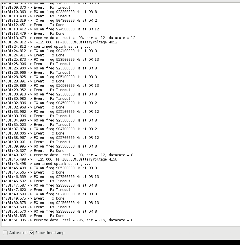
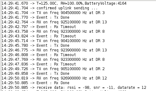
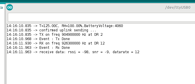
    Serial.print(“T=”);
    Serial.print(temperature);
    Serial.print(“C, RH=”);
    Serial.print(humidity);
    Serial.print("%,");
    Serial.print(“BatteryVoltage:”);
    Serial.println(batteryVoltage);
    }

void setup() {
boardInitMcu();
Serial.begin(115200);
#if(AT_SUPPORT)
enableAt();
#endif
deviceState = DEVICE_STATE_INIT;
LoRaWAN.ifskipjoin();
}

void loop()
{
switch( deviceState )
{
case DEVICE_STATE_INIT:
{
#if(AT_SUPPORT)
getDevParam();
#endif
printDevParam();
LoRaWAN.init(loraWanClass,loraWanRegion);
deviceState = DEVICE_STATE_JOIN;
break;
}
case DEVICE_STATE_JOIN:
{
LoRaWAN.join();
break;
}
case DEVICE_STATE_SEND:
{
prepareTxFrame( appPort );
LoRaWAN.send();
deviceState = DEVICE_STATE_CYCLE;
break;
}
case DEVICE_STATE_CYCLE:
{
// Schedule next packet transmission
txDutyCycleTime = appTxDutyCycle + randr( 0, APP_TX_DUTYCYCLE_RND );
LoRaWAN.cycle(txDutyCycleTime);
deviceState = DEVICE_STATE_SLEEP;
break;
}
case DEVICE_STATE_SLEEP:
{
LoRaWAN.sleep();
break;
}
default:
{
deviceState = DEVICE_STATE_INIT;
break;
}
}
}

US915 downlink bandwidth is used 500K, the signal reception sensitivity will be lower.
What is the distance between the node and the gateway during the test? What gateway did you use, and is its transmit power normal?

@Xiao-H
I test wuth:
RAK7249 is 16 channels outdoor gateway installed at 36 meters of altitude.
Distance 500 meters in rural area with line of sight.
Normal power. I have 40 devices of other 2 brands working with out problems.
I have test 7 KM with other devices. This is channel config:

This is the area.

this are the gateway:


This are other devices I get over 7KM:

I want to add that I run ping-pong test with ping-pong sample with 2 capsules and I cant get more of 150 meter. After that distance I lost the communication.

@Supporter Can you help with this issue?
I cant use the devices I buy.
Please need an official position from heltec

From the first picture you attached, the problem seems the Capsule sensor already send data to the gateway, and the Capsule sensor opens the RX windows normally but didn’t get feedback every time. There may be two reasons:

  1. Capsule sends the data out, but the gateway didn’t receive it;
  2. In the US915 band, downlink messages from gateway use 500K, this will reduce the communication distance. Therefore, there is a great possibility that the gateway has received the upload, but the delivered message has not been received by the node.

For possible 1, please check with the traffic log in TTN, in the Capsule’s every send, does the traffic log show a new event?
For possible 2, when you see the TTN generated a downlink, if the Capsule didn’t print ACK information, that it.

Please do some try and location the root case, and then we find out a solution together. :slightly_smiling_face:

In next a few days, our LoRa cloud server platform will also be online and open for public beta, then you can try it on our cloud platform too.

Is that possible to get your gateway’s shell and see the message log?

Because if meet a CNC bad, gateway will not forward messages.

Please try to use 22dBm output power and use SF12.

In the USA, FCC allow LoRa output up to 30dBm.

@Supporter First of all thanks for take this case.

REPORT OF 2 CAPSULES WITH PING-PONG APP

sf12 22dbm 800 meters
sf7 22dbm 600 meters
sf7 5dbm 180 meters

I will run the gateway test now and report soon.

@Supporter
REPORT OF GATEWAY

i attach screen shoot with both cubecell serial console and gateway log in the same screen.

You can see this scenario:
1.- Cubecell TX in frequency 904.5 and gateway receive ok
2.- Cubecell open rx window in frequency 925.1 and gateway transmit in frequency 925.1 but cubecell not receive and timeout the RX window.
3.- Cubecell open a second RX window in frequency 923.3 but gateway not transmit, cubecell timeout.
4.- Cubecell TX in frequency 905.1 and gateway receive OK.
5.- Cubecell open RX window in frequency 926.9 and gateway transmit on same frequency. This time cubecell receive Ok and process done.

This process sometimes require many retry to cubecell receive. The gateway always receive the TX from cubecell.

/LoraWan channelsmask, default channels 0-15 - 64 and 65/
uint16_t userChannelsMask[6]={ 0xFFFF,0x0000,0x0000,0x0000,0x0003,0x0000 };

@Supporter friend please check my answer I urgently need to know if I can use the cubecell to buy more units. I have customer waiting for my tests.
Thanks

Sorry for the late reply, I will back here tomorrow.

Refer from the screen shot you sent, the RSSI value is very low, Already close to the limit. Because the node upload use 125KHz and the download from gateway is 500KHz. So it’s easy cause node lost message from gateway. We are consider add a PA or FEM in the receiver path…

Anyway, do you have a CubeCell series development board near your hand (for example HTCC-AB01, HTCC-AB02, etc.)? Can you have a try if the development board reach a far distance?

Yes I have 20 units of HTCC-AB01 In fact this test I do with that board.
I will run ping-pong test with HTCC-AB01 now.

REPORT OF PING-PONG TEST WITH HTCC-AB01 (take me 3 hours to make :>)
The “base” station was at 5 meters high.

First I try to use SF12 with 22 dBm and the receiver not get any transmission. If i down dBm to lower value like 15 its work.

In sumary with 15dBm and SF7 my long distance was 612 meters and with SF12 long distance 1100 1.1 KM.
I think is not too much fo rural clean area. And is weird that not work with 22dBm and SF12.

Test using 15dBm and SF7
Distance RSSI
5 CM -22
150 CM -50
30 MT -56
80 MT -54
120 MT -66
285 MT -92
612 MT -109
1100 MT Out of range

Test using 15dBm and SF12
Distance RSSI
5 CM -30
150 CM -35
30 MT -49
80 MT -54
120 MT -74
285 MT -90
612 MT -99
1100 MT -107

This was the code

/* Heltec Automation Ping Pong communication test example
 *
 * Function:
 * 1. Ping Pong communication in two CubeCell device.
 * 
 * Description:
 * 1. Only hardware layer communicate, no LoRaWAN protocol support;
 * 2. Download the same code into two CubeCell devices, then they will begin Ping Pong test each other;
 * 3. This example is for CubeCell hardware basic test.
 *
 * HelTec AutoMation, Chengdu, China
 * 成都惠利特自动化科技有限公司
 * www.heltec.org
 *
 * this project also realess in GitHub:
 * https://github.com/HelTecAutomation/ASR650x-Arduino
 * */

#include "LoRaWan_APP.h"
#include "Arduino.h"

/*
 * set LoraWan_RGB to 1,the RGB active in loraWan
 * RGB red means sending;
 * RGB green means received done;
 */
#ifndef LoraWan_RGB
#define LoraWan_RGB 0
#endif

#define RF_FREQUENCY                                915000000 // Hz

#define TX_OUTPUT_POWER                             15       // dBm

#define LORA_BANDWIDTH                              0         // [0: 125 kHz,
                                                          //  1: 250 kHz,
                                                          //  2: 500 kHz,
                                                          //  3: Reserved]
#define LORA_SPREADING_FACTOR                       12         // [SF7..SF12]
#define LORA_CODINGRATE                             1         // [1: 4/5,
                                                          //  2: 4/6,
                                                          //  3: 4/7,
                                                          //  4: 4/8]
#define LORA_PREAMBLE_LENGTH                        8         // Same for Tx and Rx
#define LORA_SYMBOL_TIMEOUT                         0         // Symbols
#define LORA_FIX_LENGTH_PAYLOAD_ON                  false
#define LORA_IQ_INVERSION_ON                        false


#define RX_TIMEOUT_VALUE                            1000
#define BUFFER_SIZE                                 30 // Define the payload size here

char txpacket[BUFFER_SIZE];
char rxpacket[BUFFER_SIZE];

static RadioEvents_t RadioEvents;
void OnTxDone( void );
void OnTxTimeout( void );
void OnRxDone( uint8_t *payload, uint16_t size, int16_t rssi, int8_t snr );

typedef enum
{
LOWPOWER,
RX,
TX
}States_t;

int16_t txNumber;
States_t state;
bool sleepMode = false;
int16_t Rssi,rxSize;


void setup() {
boardInitMcu( );
Serial.begin(115200);

txNumber=0;
Rssi=0;

RadioEvents.TxDone = OnTxDone;
RadioEvents.TxTimeout = OnTxTimeout;
RadioEvents.RxDone = OnRxDone;

Radio.Init( &RadioEvents );
Radio.SetChannel( RF_FREQUENCY );
Radio.SetTxConfig( MODEM_LORA, TX_OUTPUT_POWER, 0, LORA_BANDWIDTH,
                               LORA_SPREADING_FACTOR, LORA_CODINGRATE,
                               LORA_PREAMBLE_LENGTH, LORA_FIX_LENGTH_PAYLOAD_ON,
                               true, 0, 0, LORA_IQ_INVERSION_ON, 3000 );

Radio.SetRxConfig( MODEM_LORA, LORA_BANDWIDTH, LORA_SPREADING_FACTOR,
                               LORA_CODINGRATE, 0, LORA_PREAMBLE_LENGTH,
                               LORA_SYMBOL_TIMEOUT, LORA_FIX_LENGTH_PAYLOAD_ON,
                               0, true, 0, 0, LORA_IQ_INVERSION_ON, true );
state=TX;
}


void loop()
{
	switch(state)
	{
		case TX:
			delay(1000);
			txNumber++;
		    sprintf(txpacket,"%s","hello");
		    sprintf(txpacket+strlen(txpacket),"%d",txNumber);
		    sprintf(txpacket+strlen(txpacket),"%s"," Rssi : ");
		    sprintf(txpacket+strlen(txpacket),"%d",Rssi);
		    turnOnRGB(COLOR_SEND,0);

		    Serial.printf("\r\nsending packet \"%s\" , length %d\r\n",txpacket, strlen(txpacket));

		    Radio.Send( (uint8_t *)txpacket, strlen(txpacket) );
		    state=LOWPOWER;
		    break;
		case RX:
			Serial.println("into RX mode");
		    Radio.Rx( 0 );
		    state=LOWPOWER;
		    break;
		case LOWPOWER:
			lowPowerHandler();
		    break;
    default:
        break;
	}
Radio.IrqProcess( );
}

void OnTxDone( void )
{
	Serial.print("TX done......");
	turnOnRGB(0,0);
	state=RX;
}

void OnTxTimeout( void )
{
Radio.Sleep( );
Serial.print("TX Timeout......");
state=TX;
}
void OnRxDone( uint8_t *payload, uint16_t size, int16_t rssi, int8_t snr )
{
Rssi=rssi;
rxSize=size;
memcpy(rxpacket, payload, size );
rxpacket[size]='\0';
turnOnRGB(COLOR_RECEIVED,0);
Radio.Sleep( );

Serial.printf("\r\nreceived packet \"%s\" with Rssi %d , length %d\r\n",rxpacket,Rssi,rxSize);
Serial.println("wait to send next packet");

state=TX;
}

Hi, for Capsule AC0X, there is another way you can have a try, let’s have a look if will be better: Modify the US915_RX_MAX_DATARATE to DR_8 (default is DR_13)

Anyway, just have a try, I didn’t test at my side.:slightly_smiling_face:

If I recall, the default LoRaWAN max output power use 17dBm. Refer from the ping-pong test result, the CubeCell AB01 board have a better antenna than Capsule sensor…

Did you try the AB01 communication with gateway? What’s the max distance?

Hello. I make the test with AB01 with gateway. The difference if very big from capsule.

I can tell you that AB01 have more capacity to transmit that sensibility to receive.

My test was in rural area very open without terrain mountains or mountains.

In general the test was not bad but if I compare with other devices is a little below.

I tried with the included antenna and also with 2 higher gain antennas in the far places. As for the reception it is increased a little (very little), but in the transmission it is greatly increased. But it is useless to gain transmission if the reception sensitivity does not increase.

My test consist in 7 samples between 10 meters and 8.05 kilometres.

This was result

Base station
https://maps.google.com/maps?q=-36.79058837890625%2C-72.38048553466797&z=17&hl=es
RAK7249
Tower with 36 meters height.
card: SX1301
Tx Power: up to 25dBm
Rx sensitivity: -142dBm (Min).
Antenna: 3dBi
Channels: 8 Channels 
------------

10 meters plus tower height 36 mt:
rssi: -59
snr: 9
bandwidth: 125
sf: 7
cr: 4/5
frequency: 903.3
------------

1.14 kilometres:
https://maps.google.com/maps?q=-36.78232955932617%2C-72.37358093261719&z=17&hl=es
rssi: -96
snr: 9.3
bandwidth: 125
sf: 7
cr: 4/5
frequency: 903.1
------------


1.77 kilometres:
https://maps.google.com/maps?q=-36.78253936767578%2C-72.36382293701172&z=17&hl=es
rssi: -87
snr: 9.3
bandwidth: 125
sf: 7
cr: 4/5
frequency: 903.7
------------

2.92 kilometres:
https://maps.google.com/maps?q=-36.782501220703125%2C-72.349609375&z=17&hl=es
rssi: -105
snr: -1
bandwidth: 125
sf: 7
cr: 4/5
frequency: 902.7
------------

5.57 kilometres:
https://maps.google.com/maps?q=-36.78631591796875%2C-72.31855010986328&z=17&hl=es
rssi: -98
snr: 9.3
bandwidth: 125
sf: 7
cr: 4/5
frequency: 902.7
------------

6.87 kilometres:
https://maps.google.com/maps?q=-36.769508361816406%2C-72.30838012695312&z=17&hl=es
rssi: -110
snr: 5.8
bandwidth: 125
sf: 8
cr: 4/5
frequency: 903.5
------------

8.05 kilometres:
https://maps.google.com/maps?q=-36.75694274902344%2C-72.30085754394531&z=17&hl=es
*** Gateway receive the transmission from the node but node not receive the answer from gateway so can not complete join operation ***
Gateway receive with rssi: -110
Gateway snr: 4.5
Gw bandwidth: 125
Gw sf: 7
Gw cr: 4/5
frequency: 903.5

Here I change antenna for more gain antenna in node and gateway receive with more good rssi but node can not receive to the gateway.
RSSI in gateway increase to: -80
------------