Good day
Can i get some clarity on the pinouts below
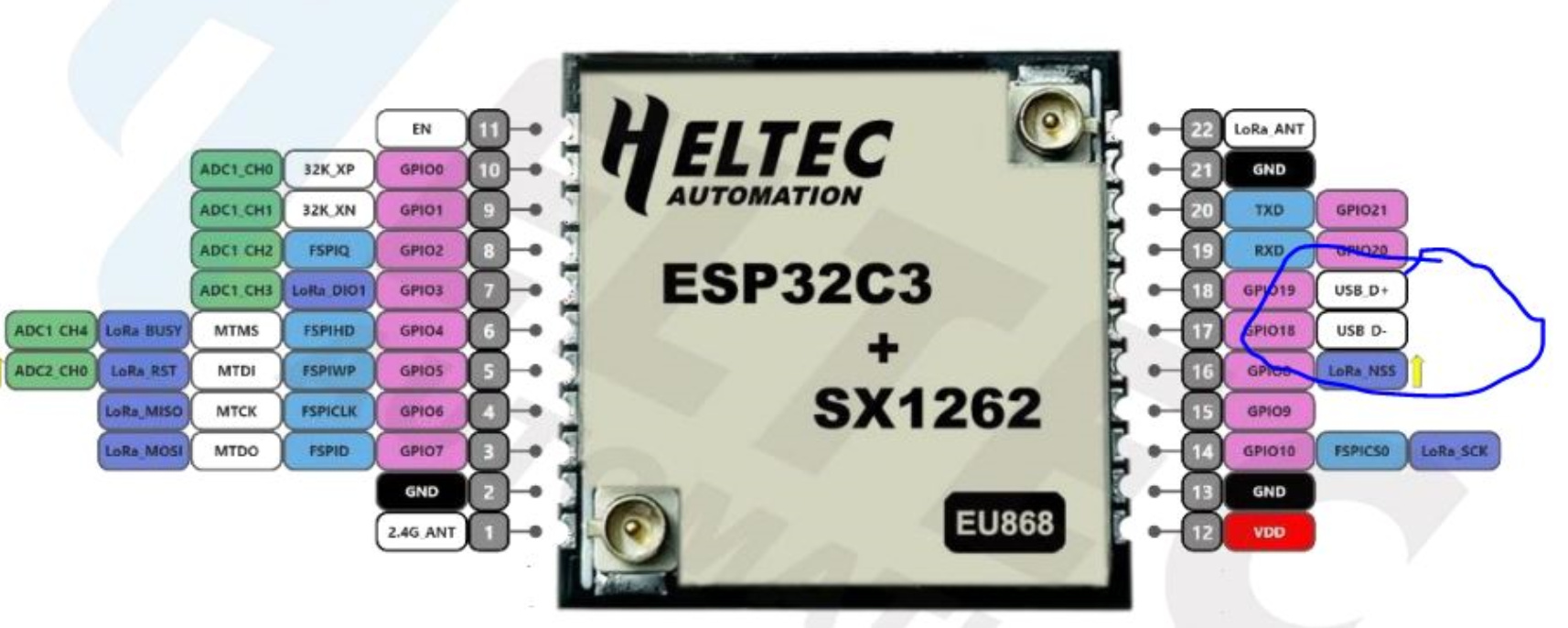
Can you use the USB D+ and USB D- for connection to Micro USB connector direct?
The reference document shows USB to serial option
Thanks

Good day
Can i get some clarity on the pinouts below
Can you use the USB D+ and USB D- for connection to Micro USB connector direct?
The reference document shows USB to serial option
Thanks
I too have question regarding USB Pins on this HT-CT62 module. On ESP32-C3 modules USB can be used for programming and debugging of the CPU for sure. I confirm this because i have a custom designed board based on ESP32-C3-MINI module which uses USB interface for program and debug.
However when i hooked up external USB connector to HT-CT62 module using ESP Dev Backplane. My computer running Windows 10 was unable to detect USB Com port.
My connection scheme was like following:
USB ------ ESP DEV BACKPLANE
USB_D+ ---- GPIO19
USB_D- ---- GPIO18
USB5V -------5V
GND -------- GND
Maybe GPIO18 and GPIO19 are not available as USB interface pins on Heltec HT-CT62 module?
Ok, i was able to run USB interface of the HT-CT62 module with above connection diagram. I was mistakenly connecting to wrong IOs while i typed my previous message.
Hi,
I am trying to boot up the HT-CT62 without success.
The short question is:
Does anyone know what is the exact sequence to power up and load code to the chip? (HW and SW wise) I already pulled-up EN and USER pins. Are there any additional boot strap pins that I need to connect? or sequence of high/low of these pins? and also what is the baud rate and serial port settings.
The longer story and all the data I have accumulated:
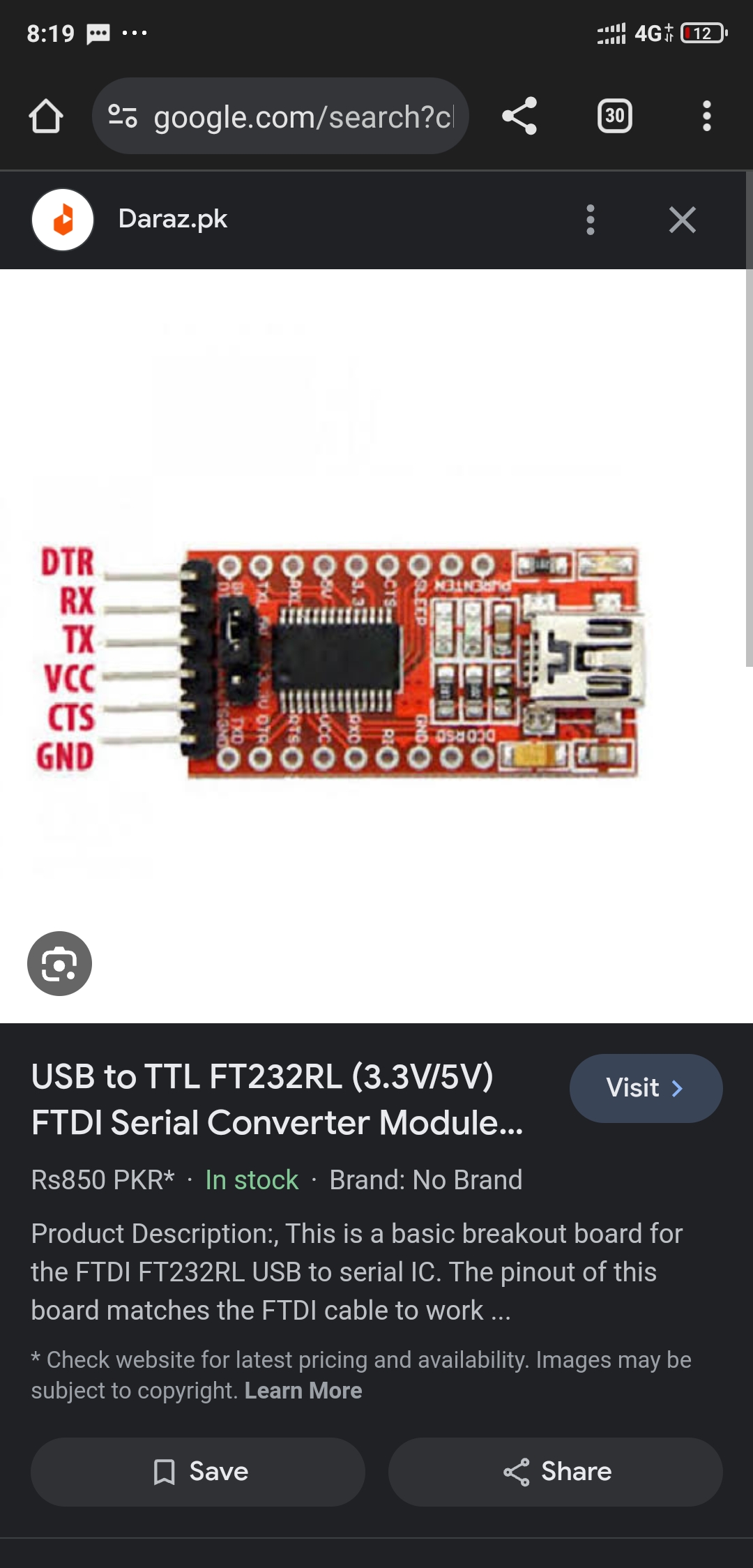
To solve the issue, I was recommended by the Heltec support team to use the serial interface by the connected to a USB to Serial adaptor based on an cp2102 chip. (rather than connecting directly to the USB D+ D- USB pins), it is indeed simpler because the direct connection to the USB requires some special care about power, ground, and cabling.
I was also told by the Heltec support team that I need to pull-up the EN pin (pin 11) and the USER pin (pin 16 GPIO8). to get to a boot load.
So,
I connected the following:
TXD (pind GPIO21, pin 20) to the usb adaptors Rx,
RXD(GPIO20, pin 19) to the adaptor Tx respectively.
pull-up the EN pin (pin 11)
pull-up the USER pin (GPIO9, pin11)
That did not work
But in a certain sequence of playing with these two pins, I do see activity on the TXD pin going out of the chip, so it gives me some hope.
To be exact, if i power cycle the module with these two pins pulled up, I see some activity on the TXD for a short period. After that, if I release the EN pin, I see activity on the TXD pin, and if I pull it up again I also see activity. not sure what it means… but the CPU seems to do something, it is not dead.
TXD(GPIO21)—Serial Rx
RXD(GPIO20)–Serial Tx
EN(pin 11) - pull-up
USER(GPIO9) -pull-up
Software wise, I tried 3 different ways to connect:
1 - MACOS Terminal with the esptool:
esptool.py -p flash_id esptool.py v4.6.2
2 - Arduino, I configured the board type to be: Wireless stick lite (v3), and selected the port published by the serial adaptor
3 - two different online tools, including the Espressif own online tool
So I tried several ways, they all see the serial port that the adaptor is publishing. I do see that the serial adaptor sends data (led blinks) and I do see blinking of the other side (the ESP side) but it does not connect.
I was getting responses like:
Connecting…
Connected successfully.
Try hard reset.
And then i tried to play a bit with the EN/USER pins but nothing really helped.
I was trying to send emails to Heltec support team, they are supportive, but I get short answers without explanations, once every few days, so, I am not succeeding to make a real breakthrough.
My question is: does anyone know what is the exact sequence to power up and load code to the chip from scratch? Are there any additional boot strap pins that I need to connect? what is the baud rate and serial port settings. In other words,
Much appreciate if someone can help.
Hello,
I program the HT CT62 sucesfully with this configuration via external serial conveter:
USER(GPIO9) - GROUNDED
EN(pin 11) - VCC
TXD(GPIO21) - to serial USB converter
RXD(GPIO20) - to serial USB converter
Best regards,
Kuba
@asimlink can you tell me in a circuit diagram how you got it? Everyone else, i have an ftdi and ht_ct62. I tried various options but always get fatal error Esp32 not found. I do see serial but nothing in there. Can you provide pins to connect ftdi to ct?
Hello Kuba, are you sure about this?
According to reference design, GPIO21 is ground, GPIO20 is TXD and GPIO19 is RXD.
Honza
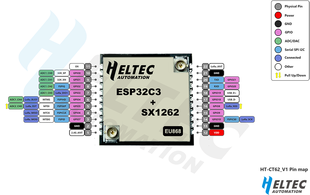
@jaybee123 you mistake the normal numbering for the GPIP numbering. The GPIO numbering is correct (https://heltec.org/wp-content/uploads/2023/09/HT-CT62.png)
Thanks. Indeed you are right 
Hello
I found that compilation error was mistake in instalation libraries in arduino.
If I want to flash GPIO9 and EN(pin11) shut be connected all the time or reconnect it after plug in?
Compilation errors are hardware independent
Hi
I would like to use the module HT-CT62 for a custom project (mashtastic based) but I don’t find in the documentation and anyware how the uController ESP32 C3 is connected internally with the Lora SX1262 transceiver
What GPIO of the C3 are used to connect to the SX1262 (SPI bus communication pin etc…)
Since I want to complile mashtastic FW on this HW I mandatory need to know how GPIO are used internally !
thanks for any suggestion
Davide
The page for the product has a pin map that shows the connections plus a link to the data sheet that shows the pin map and a link to the internal schematic which shows the internal connections.
Also, the very first post of this topic has the pin map pictured.
This may be helpful to you,
Actually this helped me to enter the flashing mode on HT62 for Meshtastic upgrade, using the USB pins of the board connected to USB directly: