Heltec Esp32 lora shell

I purchased two heltec Esp32 sx1276 ct62 shells from heltec. Using ftdi i can program Esp32 Wroom 32 using the Esp32 Dev Board on Arduino. But no luck with ct62. Do i have to use a different arduino board?
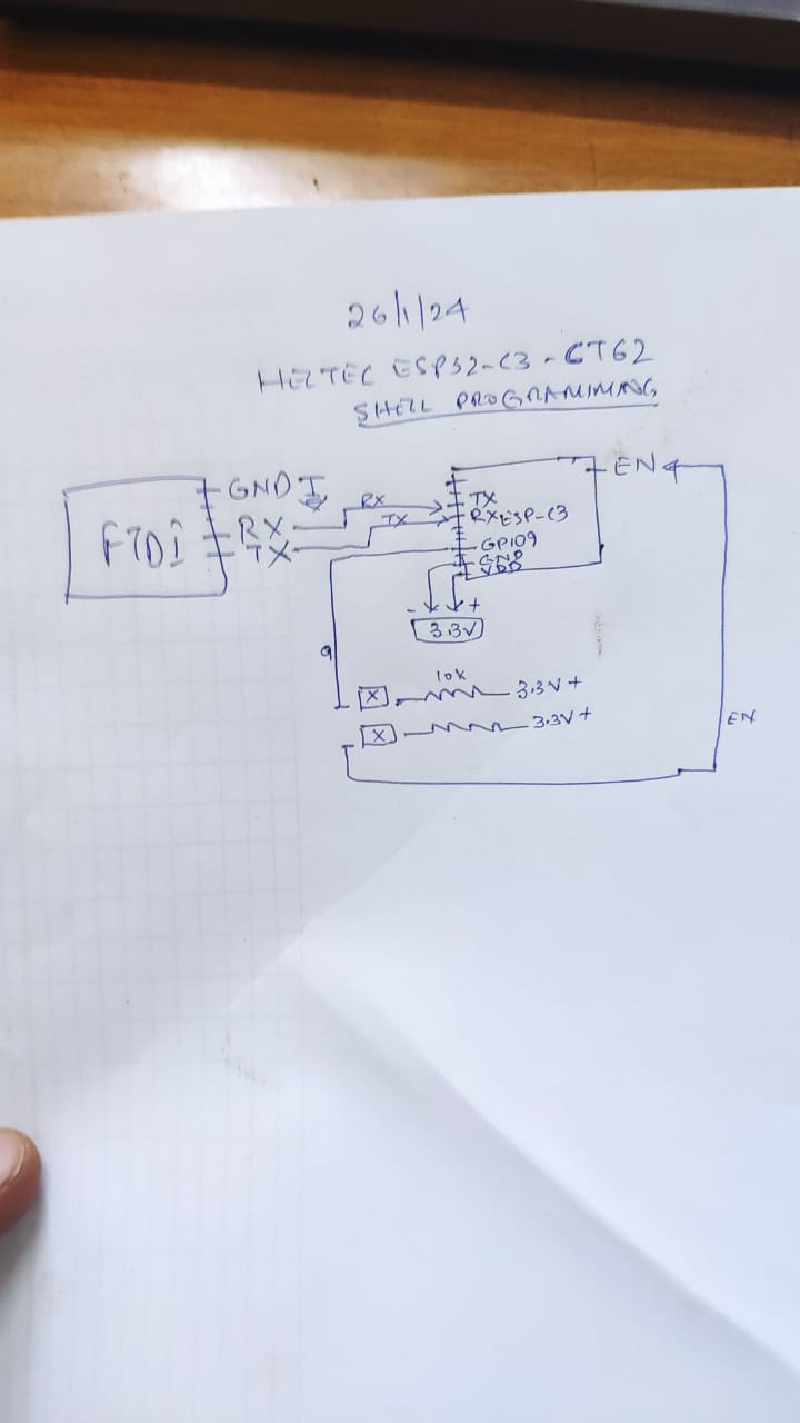
Ftdi ct62.
Rx. TXD
Tx. RXD
Gnd. Gnd
En->flash switch -> 10kohm-> 3.3v
0 -> reset switch -> 10kohm-> 3.3v
2 -> Gnd
VCC -> 3.3v
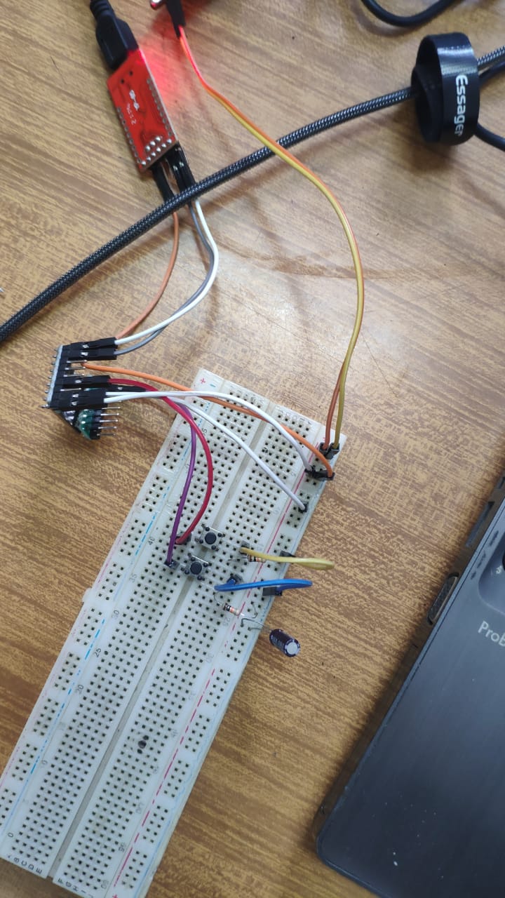
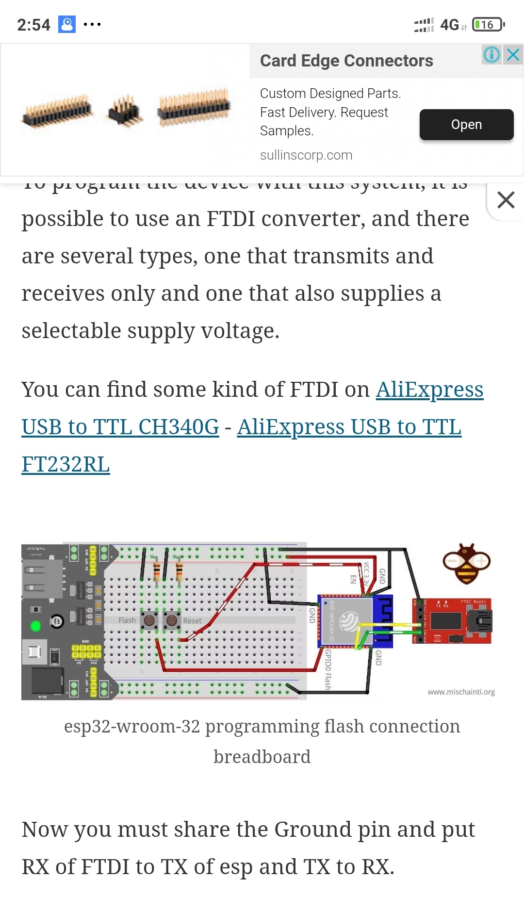
I followed the arrangements as here:


I get the error on arduino as “fatal error could not find the Esp32 dev board.”

So no luck with ct62. Do i have to use a different arduino board? Or it has to do with connections?

Are you using https://heltec.org/project/ht-ct62/ ?

If so, this is based on the ESP32-C3. Schematic of this module https://resource.heltec.cn/download/HT-CT62/HT-CT62_Schematic_Diagram.pdf it is a ESP32-C3

Following a ESP32-Wroom example probably won’t work.

Just want to be clear, I don’t have any hands on with this module but have worked with the ESP32-C3 Modules on a custom PCB.

On the C3 module I used, GPIO9 would be connected to the boot switch.
You connect the USB D+ and D- from your computer directly to GPIO18 & GPIO19. There is no need for any serial interface. Vcc still needs to be 3.3v not 5v so will need some kind of regulator.
Then follow Arduino IDE instructions for using a ESP32-C3 module for the IDE settings.

In the reference design https://resource.heltec.cn/download/HT-CT62/HT-CT62_Reference_Design.pdf they label the USB to Serial as optional.

Thanks @dstacer . Three questions

  1. You say: “On the C3 module I used, GPIO9 would be connected to the boot switch” … Is that necessary to upload a code? given that:

  2. You say: “You connect the USB D+ and D- from your computer directly to GPIO18 & GPIO19. There is no need for any serial interface. Vcc still needs to be 3.3v not 5v so will need some kind of regulator.”
    That will require some sort of ftdi/uart otherwise how will both be grounded?

  3. You say:" Then follow Arduino IDE instructions for using a ESP32-C3 module for the IDE settings."
    The ones already in preferences are: https://dl.espressif.com/dl/package_esp32_index.json

Please help

  1. Sometimes I need to use the Boot button. Most of the time no. My PCB with ESP32-­C3-­WROOM­-02 I have never needed the boot button. Second PCB that uses ESP32­-C3-­MINI-­1 module needed the boot button the first load. The boot button just forces the chip into bootloader mode expecting a download. press & hold reset switch then press boot. Next release reset switch then release boot.

  2. No FTDI/UART needed with the C3. You will need a 3.3v regulator to take the 5.0v from the USB VCC to drop it to 3.3v the ESP32-C3 requires. ME6211C33M5G or ME6119C33M5G are two examples but there are hundreds of LDO’s that would work.

  3. Pick boardtype ESP32-> ESP32 Dev-module. Flash Mode -> DIO
    USB CBC Mode -> Enabled.

When you plug the board into a computer it should show up as a com port. That is one of the first things to accomplish. My experience on Windows, if the board doesn’t show up in device manager as a COMx port you can’t load it.

Since you are using a module, are you developing a PCB for it? How is the project going to be powered? The LDO you pick for the project should supply enough current for the combined ESP32-C3 and SX1262.

Might be possible to use FTDI type of board and serial RX/TX pins, I’ve never tried. This thread https://esp32.com/viewtopic.php?f=2&t=30374 has some comments around this type of issue.

Another post for you to review: HT-CT62 - Pinout

Hope that all helps. Working with just a module alone can be frustrating because you need to get is 100% correct for it to work.

Thanks. I will try. I use usb lora modules to get data from soil sensors through rs485 to ttl. There a single 3.7v cell is enough with a 3.3v step down and a 5v step up for sensor. The modules cost $14, the shell costs $4 and hence the desire to bring down the cost for the farmers in a auto drip irrigation system.

@dstacer one confusion. You say gpio9 is to be connected to boot switch, for a shell (without boot switch) that means having s switch and a 10kohm resister to Gnd? The final.connection i understand:
Gpio9 to Gnd
GPIO18 to D+
GPIO19 to D-
3.3v from 5V usb using step down

Aurduino
Board Esp32 Dev-module
Flash DIO
Usb CBC Mode Enabled

Is that right?

Don’t need the resistor on GPIO9 just a push button switch to GND. GPIO9 is used to get into download mode. GPIO9 must be high or left floating to boot normally. Press & hold reset, press GPIO9 switch, release reset switch then release GPIO9 switch.
https://docs.espressif.com/projects/esp-hardware-design-guidelines/en/latest/esp32c3/esp-hardware-design-guidelines-en-master-esp32c3.pdf page 29 “To download via USB:” section.

I made an error in a previous post should be:
GPIO19 to D+
GPIO18 to D-

Arduino IDE Board type should be ESP32C3 Dev Module not esp32.

I may have to buy one of these to test out, don’t want to be leading you down a bad path.

It would be nice if Heltec published a few projects using this module as a solution. It would really help for this kind of project.

@dstacer I think you are forgetting that there is no switches or buttons on heltec lora shell, its just a shell with pins on it, no buttons. For the reset and flash buttons the gpio9 and EN will have to be linked to ground and 10kohm 3.3v via external switch respectively . So the pins will be:
Gpio9 to switch to Gnd
EN to switch to 10kom to 3.3v
GPIO18 to D-
GPIO19 to D+
3.3v from 5V usb using step down

Aurduino
Board Esp32C3 Dev-module
Flash DIO
Usb CBC Mode Enabled

The connections you posted should work. If you had a generic ESP32-C3 board that would work.

Are you developing on Windows? Does window show a new com port when you connect it?

Wireless shell is yet another module that is not a standalone product. It needs external components to operate just like the CT62.

Heltec sells a ESP Dev Backplane board https://heltec.org/project/esp-dev-backplane/ That will support either the CT62 and Wireless Shell.

I had to search around but found the schematic here https://resource.heltec.cn/download/HT-DEV-ESP . In that board they are using a CP2102 to interface to the ESP32-C3. That will work too. More components than I think is needed.

Wemos makes a bare bones ESP32-C3 board that works without any FTDI our CP2102 serial interface. https://www.wemos.cc/en/latest/_static/files/sch_c3_mini_v2.1.0.pdf. That is the way I have implemented a bare bones ESP32-C3 Wroom module.

I guess I’m not much help because I don’t have a CT62 to test with and was just responding because I do have experience with a bare bones ESP32-C3 and the CT62 is a barebones ESP32-C3 and SX1262.

Have you tried to engage Heltec support with your questions?

Using the ESP32C3C62 - FTDI and using ESP32Dev board in arduino with PSRAM Enabled and Flash mode DIO i used the following pins:

GPIO20 to TX
GPIO21 to RX
VDD - 3.3V
GPIO9 - switch -10kohm-3.3V
EN- - switch -10kohm-3.3V
Gnd- Gnd

It gives the following error:
This chip doesn’t appear to be a ESP32 (date codes 0x03700000:0x00000000). Probably it is unsupported by this version of esptool.
Chip is ESP32-D0WDQ6 (revision 0)
Features: WiFi, BT, Dual Core, Coding Scheme None
WARNING: Detected crystal freq 0.00MHz is quite different to normalized freq 26MHz. Unsupported crystal in use?
Crystal is 26MHz

Please help.

finally managed to upload the code to esp32c3-ct62 shell via the ftdi. I suggest you post it somewhere to help others. the last common mistake i was making was trying to upload it via Esp32 Dev Board. When i reinstalled esp32 library to version 2.0.11 it allowed the ESP32C3-Dev Module and then (with USB on CDC boot Disabled, Flash Mode DIO, JTAG Adapter Disabled) i was able to upload the code via ftdi.

The connections:

ESP32C3C62 - FTDI

GPIO20 to TX
GPIO21 to RX

VDD - 3.3V

GPIO9 - switch -10kohm-3.3V

EN- - switch -10kohm-3.3V

Gnd- Gnd

Power to the CT62 should be from external source not the ftdi. Attached are the pics of the circuit and a badly drawn diagram (something i asked for many many times almost at as many places!)

Thanks @dstacer for your help.