Heltec wireless tracker v1.1 no response

Hi All,

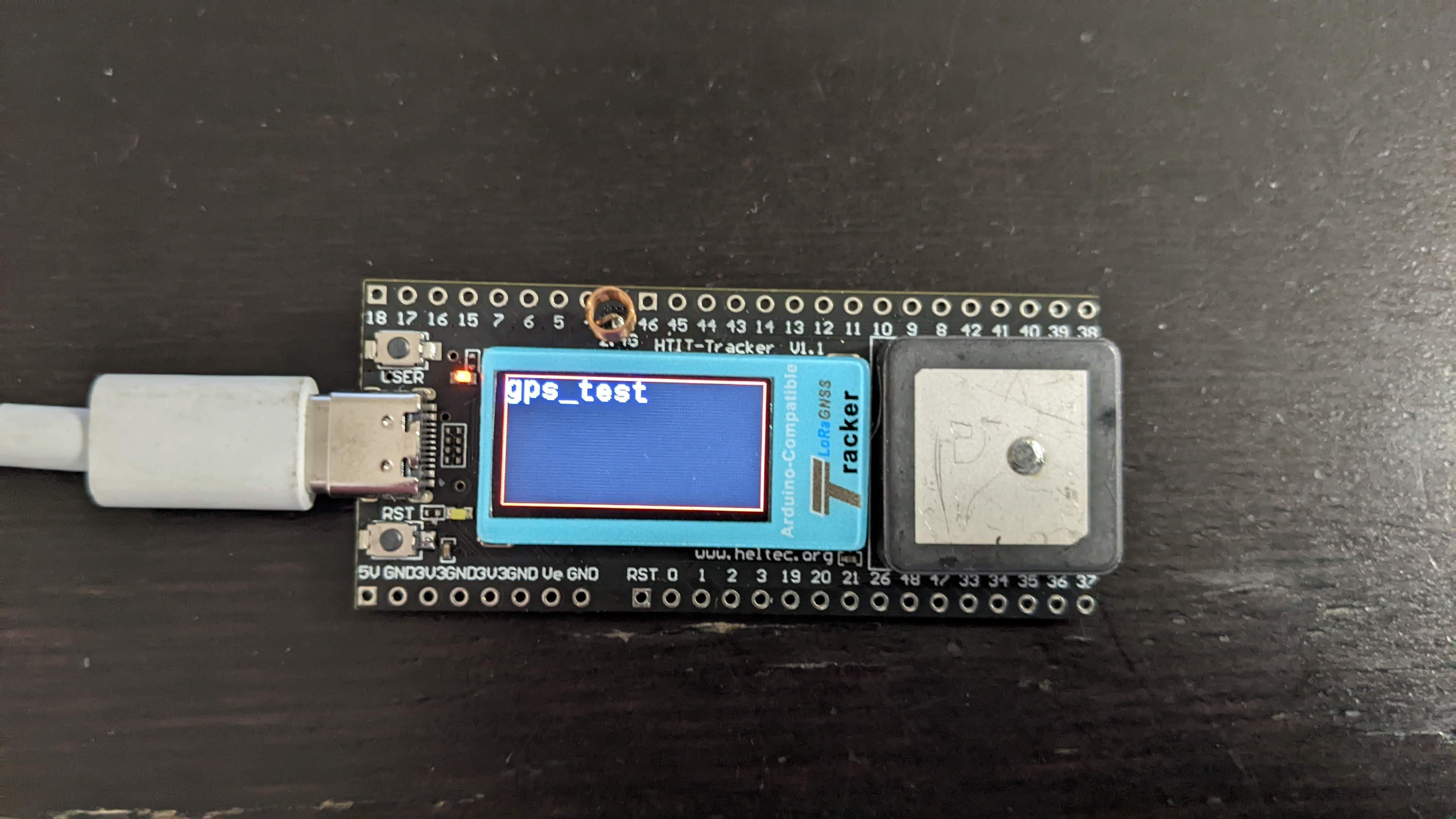
I have a v1.1 wireless tracker. When I first plugged it into my PC I had a display that told me the wifi was unable to connect. I tried for several days to get the correct version of the Heltec files installed into the Arduino IDE ( ver 0.0.8). I can finally compile the “Wireless_Track_FactoryTest.ino” without any errors. It uploads the code to the tracker, but I get no response, no display on the screen and no output to the serial monitor. An orange LED is on rather dimly near the top left of the display. The LED near the reset button is dark. Pressing the reset button makes by PC make the usb “connecting” sound.

What can I do to verify the tracker is still alive? I haven’t done anything to it other than plug it into my USBC on the laptop and attempt to upload-no soldering or anything.

Thanks!

Todd

Hey Todd!

As you can see from the topic Heltec HTIT-Tracker V1.0, I am also trying to get this thing going.
One thing for you to note, is that this board uses an ESP32-S3, which has native USB support.
The USB-C port is wired directly to this native USB line, and therefore you should not use Serial.print(), but USBSerial.print() with the corresponding USBSerial.begin() etc modified accordingly. You may want to watch https://youtu.be/hJSBTFsOnoA as an explanation regarding the different types of USB support on the S3.
Hopefully we can get this stuff going together! :slight_smile:

Cheers, Steven

Hi Steven,

Your post about loading the 0.0.8 version and changing directories etc. is the only reason I’ve gotten as far as I have! So thanks for that!! I did see the recommendation Heltec has for using a USB to UART programmer. I think I have one that I use on my other Arduinos. I think that is my next step. It might help with any cabling issues I have. Not all USBC cables are created equal!

I’m still unsure about which options to use as well. I haven’t done any research into the OTG stuff yet. Hopefully I’ll get some more time to play with it tomorrow night.

You’re welcome :slight_smile: happy to give back to the community!
You shouldn’t need a programmer nor really have to dig into all USB modes.
All you should need to do, is change any reference to Serial into USBSerial and you’ll see that the device is still alive.
As long as your USB cable is capable of uploading to the board, it’ll work fine for serial communication.

Hurray, more success: display working!

Edit the following file:

  • C:\Users\{user}\AppData\Local\Arduino15\packages\Heltec-esp32\hardware\esp32\0.0.8\libraries\DISPLAY\src\HT_st7735.h

Pin definitions should read as follows:

/*** Redefine if necessary ***/
#define ST7735_CS_Pin        38
#define ST7735_REST_Pin      39
#define ST7735_DC_Pin        40
#define ST7735_SCLK_Pin      41
#define ST7735_MOSI_Pin      42
#define ST7735_LED_K_Pin     21
#define ST7735_VTFT_CTRL_Pin -1

Edit the following file:

  • C:\Users\{user}\AppData\Local\Arduino15\packages\Heltec-esp32\hardware\esp32\0.0.8\variants\wireless_track\pins_arduino.h

Line 74 should read as follows:

static const uint8_t Vext = 3;

In your .ino file, the VextON() and VextOFF() should read as follows:

void VextON(void)
{
  pinMode(Vext,OUTPUT);
  digitalWrite(Vext, HIGH);   // active HIGH
}

void VextOFF(void)
{
  pinMode(Vext,OUTPUT);
  digitalWrite(Vext, LOW);
}
1 Like

Maybe just check those suggestions there in relation to switching Vext ON and OFF.

Heltec haven’t helped the situation with their pin labelling in this case, but the pin identified as Vext in the pins_arduino.h file, the one usually referred to when coding, is usually actually the pin identified as Vext Control or Vext_Ctrl (Heltec is not consistent in their documentation in this regard either) in pinout diagrams, not the Vext power pin itself. Vext_Ctrl, in turn, is used to control a MOSFET that switches Vext ON or OFF, and this is where the confusion arises. To switch Vext ON, Vext_Ctrl (which is identified in the pins_arduino.h file, and hence in your code, as Vext) is set LOW, and to switch Vext OFF, Vext_Ctrl is set HIGH.

There was also a recent thread in relation to one of the other Heltec boards that indicated that, in spite of what might have been suggested in the relevant schematic diagram, the OLED display is not powered through Vext.

None of this is based on any understanding to the Wireless Tracker board, but given that it applies to other Heltec boards, it may be relevant in the present case.

USBSerial.begin Is throwing a “USBSerial” was not declared in this scope. Do I need to include a different library? All I have found is references to SerialUSB.

Hi Todd, do you have the same values set in the Tools menu of the Arduino IDE?
image

Yes I do! I also have USB CDC on Boot =enabled. I tried it disabled but still no joy.

Hmm, interesting. But you are able to program the board?
If so, could you then try to get the display alive using the edits I proposed?

I added a: #define USBSerial Serial

which gets it to comlile but the board is still “Dead”.

I have the edits you mentioned above completed. I went through the schematic last night and I see why you changed some of the pin numbers and the Vext.

Do you have access to a multimeter (or an LED with a resistor)?

What happens with the following sketch?

#define Vext 3

void setup() {
  pinMode(Vext, OUTPUT);
}

void loop() {
  digitalWrite(Vext, HIGH);
  delay(5000);
  digitalWrite(Vext, LOW);
  delay(5000);
}

(of course, measure the voltage difference over Ve and GND / plug a LED into those)

1 Like

That works! I should have thought of that test! I added in a serial.begin and was able to print to the serial port. USBSerial still wont compile. Now I’ll try to add in the display.

I just added in the init and include for the display and now the back light is flashing with the Vext pin! Making progress!

1 Like

I have a Display!

I made my own stripped down test for the display since the examples still don’t seem to work. I don’t understand how the examples are controlling the Vext pin. The tracker V1.1 schematic (V0.5?) shows the Vext Ctrl signal enabling a 3.3V LDO, which powers the display and the backlight. The back light also has a Mosfet controlled by LED K from the MCU. I have not figured out how LED K is being enabled as I am not doing anything with it. Maybe the ST7735 init function? Maybe it defaults On somehow?

My discovery was making sure Vext was high before I allowed the display enable function. I am using all of the changes listed above by @bns -Thank you Sir!

My working code:

#include "HT_st7735.h"
#include "Arduino.h"
HT_st7735 st7735;

void setup() {
  pinMode(Vext, OUTPUT);
  digitalWrite(Vext, HIGH); //LCD needs power before init.
  Serial.begin(115200);
  st7735.st7735_init();
  Serial.printf("Ready!\r\n");
}

void loop() {
  // Check border
    st7735.st7735_fill_screen(ST7735_BLACK);
    st7735.st7735_write_str(0, 0, (String)"gps_test");
    Serial.print("made it to BLACK");

    for(int x = 0; x < ST7735_WIDTH; x++) {
        st7735.st7735_draw_pixel(x, 0, ST7735_RED);
        st7735.st7735_draw_pixel(x, ST7735_HEIGHT-1, ST7735_RED);
    }

    for(int y = 0; y < ST7735_HEIGHT; y++) {
        st7735.st7735_draw_pixel(0, y, ST7735_RED);
        st7735.st7735_draw_pixel(ST7735_WIDTH-1, y, ST7735_RED);
    }

    delay(3000);

}
1 Like

I added the two lines below to set Vext high and the Heltec example ST7735_SPI.ino is now working too. I feel like there is a better way to do this. I’m not a coder so I’ll be struggling along.

void setup()
{  
    pinMode(Vext, OUTPUT);
    digitalWrite(Vext, HIGH); //LCD needs power before init?
    st7735.st7735_init();
    Serial.printf("Ready!\r\n");
    Serial.begin(115200);

Your insistence that setting ‘Vext’ HIGH enabled Vext really troubled me but now, having access to the schematic diagram, I can see that the Wireless Tracker is different to other Heltec boards. In this case, Vext is not controlled by a MOSFET, which is switched on by setting ‘Vext’ LOW, but rather now appears to be directly connected to its own regulator, which is indeed enabled by setting ‘Vext’ HIGH—a bit of a trap for old players there…

Perhaps it should then also be no surprise if the OLED display is actually powered through Vext in this case.

1 Like

I have everything in the Wireless tracker factory test.INO functioning except for the LoRa radio. I’m not sure what to do next with it. I’m in the US at 915Mhz, beyond that I’m not sure what settings to use or how to connect to a network. I had found a page that is using the Helium network but I’m not sure if that’s what I need or not. The end result is intended to be a Vehicle tracker in case of theft.

Great to hear you’ve got it all going! :smiley:
I actually managed just fine to get my device talking to TTN - just copy the set of EUIs/keys, set a more appropriate dutycycle and disable confirmed uplinks.
I am however located in the 868MHz zone, so all other parameters were correct by default.
Are you eyeing to use TTN as well?

TTN does not seem to be very prevalent around here (North Texas) There are quite a few helium gateways here. I went through a document helium has for the Cubecell. I copied the code and started going through clearing all the compile errors since its for a V2? esp32. but I cant get it working. I also found the LoRaWAN_Downlinkdatahandle.INO from Heltec and it does compile. I added the Device and App EUI’s I got from Helium and the App key, but it fails to connect. I drove the Wireless tracker to the street where the closest gateway is and it still wont connect. I don’t know which of the myriad of settings I have wrong.