
After examining the schematic of the WiFi LoRa (V3) board it shows that the OLED display is powered by pin36 which clearly isn’t true. A small sketch switching the pin 36 from high to low doesn’t affect the display at all. I have measured the output of this pin and it behaves as expected. Is the OLED display powered from a different pin or has it just got a permanent supply? This would make it really bad for battery applications. I really need an accurate schematic.
WiFi LoRa 32 (V3) Vext not connected to pin gpio36
Thanks for the reply but the schematic doesnt make sense to me.
I am runniing the sketch below setting Vext gpio pin 36 from on to off every 2 seconds
In theory the display should only show a “1” in the display as when “0” it should have no power and should display nothing.
I have measured with a multimeter the output of Vext (gpio36) and it goes from 3 volt to 0 volt every 2 seconds so the sketch seems to be working as expected.
#include “HT_SSD1306Wire.h”
int myval = 0;
SSD1306Wire display(0x3c, 500000, SDA_OLED, SCL_OLED, GEOMETRY_128_64, RST_OLED); // addr , freq , i2c group , resolution , rst
void setup() {
pinMode(Vext, OUTPUT);
Serial.begin(115200);
VextON();
delay(100);
display.init();
}
void VextON(void) {
digitalWrite(Vext, HIGH);
}
void VextOFF(void) {
digitalWrite(Vext, LOW);
}
void Demo() {
myval = digitalRead(Vext);//read value of Vext pin 36
Serial.println(myval);//send value of Vext to com port
display.drawString(0, 0, String(myval));// show value on screen
}
void loop() {
VextOFF();
display.clear();
Demo();
display.display();
delay(2000);
VextON();
display.clear();
Demo();
display.display();
delay(2000);
}
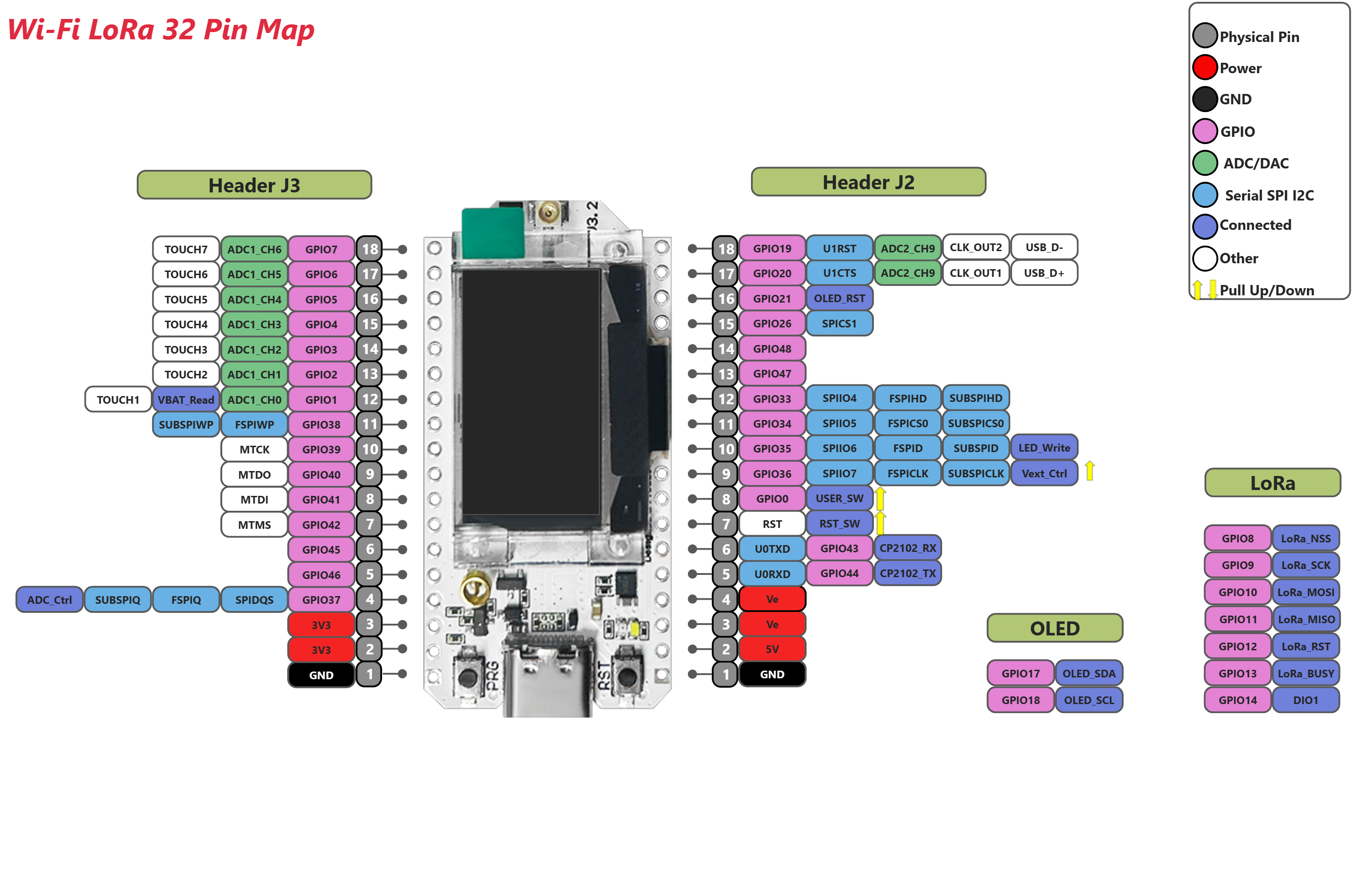
Vext is shown as being gpio36 but doesnt seem to control the display.
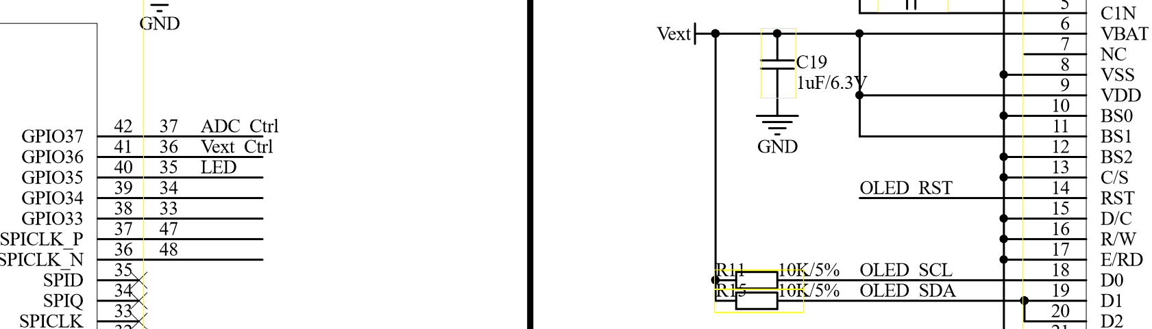
As a point of clarification here, GPIO36 is the Vext-Ctrl pin, not Vext as such. Vext is switched ON and OFF through a MOSFET, which is controlled by GPIO36. Regardless, and in spite of what appears in the Schematic, I agree that the OLED display does not appear to be powered through Vext.
For what it might be worth, I turn the OLED display off explicitly via:
display.displayOff();
then back on again if/when required via:
display.displayOn();
noting that the OLED display needs to be (re)initialised any time it is turned ON, just as it would otherwise be in the setup() function.
Thanks UniquePete for the clarification on the Vext-Ctrl pin. I was a little concerned that display.displayOff wouldn’t fully power down the display but difficult to know what is happening as it doesnt seem to be documented. I have requested clarification from Heltec so will post here if I get more detail.
From the pin map (https://resource.heltec.cn/download/WiFi_LoRa_32_V3/Wi-Fi_LoRa32_V3.2_Pinmap.png) the Vext_Ctrl is pulled up: This means the backlight goes ON when the GPIO36 is driven LOW.
In this way the backlight is always OFF when the GPIO36 is not actively kept LOW.
With below micropython code its possible to force the oled backlight on and off, by leveraging on the Vext_Ctrl pin (GPIO36):
from machine import SoftI2C, Pin
import ssd1306
import time

# Initialize the white LED pin
white_led = Pin(35, Pin.OUT)

# Initialize the OLED reset pin
oled_rst_pin = Pin(21, Pin.OUT, value=1)

# Set I2C pins in open_drain mode (if set high the pin is in a high-impedance state)
oled_sda_pin=Pin(17, Pin.OPEN_DRAIN)
oled_scl_pin=Pin(18, Pin.OPEN_DRAIN)

# Set the OLED reset pin to a high level, otherwise the display will not respond
oled_rst_pin=Pin(21, Pin.OUT, value=1)

# i2c object
i2c=SoftI2C(sda=oled_sda_pin, scl=oled_scl_pin)

# reconfigure the pin with internal Pull-up
oled_sda_pin.init(Pin.OPEN_DRAIN, pull=Pin.PULL_UP)
oled_scl_pin.init(Pin.OPEN_DRAIN, pull=Pin.PULL_UP)

# Scan the I2C bus
scan_result = i2c.scan()
if len(scan_result) == 1:
    print(f"OLED I2C device found at {hex(scan_result[0])}")

# Initialize the OLED display
display = ssd1306.SSD1306_I2C(128, 64, i2c, addr=0x3C, external_vcc=False)

# Turn on the Oled backlight
backlight_pin.value(0)  # Drive low to enable backlight

# Display a simple message
display.fill(0)
text = "Display I2C"
display.text(text, 0, 22, 1)
text = "address:" + str(hex(int(scan_result[0])))
display.text(text, 0, 38, 1)
display.show()

# Turn off the backlight after a delay
time.sleep(5)                # Keep the backlight on for 5 seconds
backlight_pin.value(1)       # Drive high to disanable backlight

# Flash a couple of times the white led, right after the oled backlight is set off
for i in range(2):
    white_led.value(1)
    time.sleep(0.2)
    white_led.value(0)
    time.sleep(0.2)

# once the micropython script ends, the GPIO36 (Vext_Ctrl) is released
# GPIO36 is externally pulled up, therefore the oled backlight goes off