Error programming CubeCell HTCC AB-01 board in Arduino

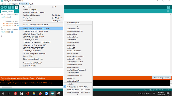
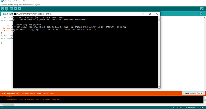
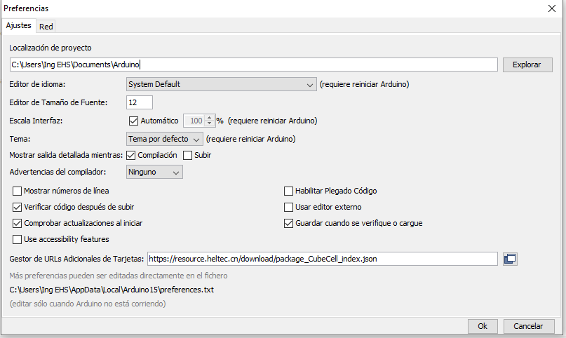
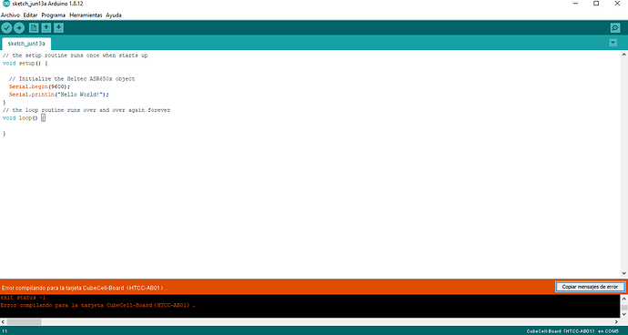
Hello everyone, I must carry out a project where I must remotely control an electrovalve using the LoRaWAN protocol. I am working with a Ursalink UG87 Gateway which is already registered in TTN and I have CubeCell HTCC AB-01 (Heltec) modules, these LoRa nodes can be programmed in Arduino. I am new working on this protocol and with these nodes, I really have no idea what pins I should use, how I should feed it, etc. I followed the steps given by the Heltec quick guide, I only connected the board to the USB port of the pc and I loaded it with a simple code (Hello World!) But it throws error. I tested the code on an Arduino UNO board and it worked perfectly. I would like to know why this happens if I clearly followed the steps given by the guide, install the CubeCell Development Framework on Arduino, the USB driver, install Git and I have Arduino IDE 1.8.12 and Python 3.8.3 installed, I have Windows 10. I want to know if I am doing something wrong or what should I do. Attached also screenshots. Thanks in advance. The error is as follows:

“C: \ Users \ Ing” is not recognized as an internal or external command,

program or executable batch file.

[12440] Failed to execute script CubeCellelftool

Traceback (most recent call last):

File “CubeCellelftool.py”, line 3, in

File “elftool.py”, line 26, in elftool.main

FileNotFoundError: [Errno 2] No such file or directory: ‘C: \ Users \ INGEHS ~ 1 \ AppData \ Local \ Temp \ arduino_build_518860 / sketch_jun13a.ino.hex’

exit status -1
Compiling error for CubeCell-Board (HTCC-AB01)

Seems the user name of your computer have a space?

Hello, I already solved the problem. Change computer and when loading the Hello World! the HTCC AB-01 worked perfectly.

Now I tried one of the examples given by LoRa but it doesn’t work. The example is LoRaSender and I get the following error:

Arduino: 1.8.13 (Windows 8.1), Card: “CubeCell-Board (HTCC-AB01), REGION_US915, CLASS_A, OTAA, ON, CONFIRMED, OFF, ON, ACTIVE, None”

In file included from D: \ data saved July 5, 2016 \ users \ user \ Documents \ Arduino \ libraries \ LoRa \ src / LoRa.h: 8: 0,

             from D: \ data saved July 5, 2016 \ users \ user \ Desktop \ LoRaSender \ LoRaSender.ino: 2:

C: \ Users \ User \ AppData \ Local \ Arduino15 \ packages \ CubeCell \ hardware \ CubeCell \ 1.0.0 / cores / asr650x / SPI / SPI.h: 31: 7: error: redefinition of ‘class SPIClass’

class SPIClass

   ^

In file included from D: \ data saved July 5, 2016 \ users \ user \ Desktop \ LoRaSender \ LoRaSender.ino: 1: 0:

C: \ Users \ User \ AppData \ Local \ Arduino15 \ packages \ CubeCell \ hardware \ CubeCell \ 1.0.0 / cores / asr650x / SPI / SPI.h: 31: 7: error: previous definition of ‘class SPIClass’

class SPIClass

   ^

In file included from D: \ data saved Jul 5, 2016 \ users \ user \ Desktop \ LoRaSender \ LoRaSender.ino: 2: 0:

D: \ data saved July 5, 2016 \ users \ user \ Documents \ Arduino \ libraries \ LoRa \ src / LoRa.h: 112: 3: error: ‘SPISettings’ does not name a type

SPISettings _spiSettings;

^

exit status 1

Compiling error for CubeCell-Board (HTCC-AB01) card.
This report could contain more information with
“Show verbose output during compilation”
option enabled in File -> Preferences.

What I can do.

it seems library conflicted. you can try remove the library “\ users \ user \ Documents \ Arduino \ libraries \ LoRa”

Hi Aaron.Lee, I already tried the LoRa Sender code and it worked perfectly. Now I want to connect the CubeCell HTCC AB-01 node to TTN but I have not succeeded. I generated the same Device EUI, Application EUI and App Key in the node (with the code LoRaWan_downlinkdatahandle.ino) and in TTN.
I send screenshots as evidence. What should I do? How should I do it?

I would also like to ask something else: yesterday I soldered the pin rule to the board, then connect the HTCC module to the USB port of the pc and the led next to the microUSB input turned on normally, I also measured the voltage of the pins: Vs = 5VDC, 3V3 = 3.3VDC, VIN = 5 VDC, Ve = 0VDC, then I tried the Hello World code again and it worked fine. But today I connected the HTCC AB-01 module to the USB port of the pc and the LED next to the microUSB input of the LoRa module did not light up, I uploaded the Hello Wolrd code again and it worked fine, then I measured voltages of the pins and I got the following values: Vs = 2VDC, 3V3 = 3.3VDC, VIN = 5VDC, Ve = 0 VDC, as you can see the only voltage value that changed was that of Vs (down 3 VDC) and I’m concerned about the fact that the indicator LED of the LoRa module is not working. I would like to know what may be happening, since the day before everything worked very well, , and how can I solve it.

Thanks for your help. I wait fast answer.

can you post a pic of your board where we can see the solder point for the pin headers you have soldered?
perhaps you have a little solderbridge.

Hello, thanks for answering.

Yes of course. Attached .zip file where are the pictures I took to the node. The file is called CubeCell HTCC AB-01.zip

Also attached .rar where are the screenshots of the connection of the CubeCell HTCC AB-01 node to TTN, which has not worked for me. The file is called Connection to TTN.rar

The compressed files are uploaded to a Drive account. They can be accessed through the following link:

https://drive.google.com/drive/folders/1Y_9YdbZXeiHmV26RAnCaHvcwdaT-rwb5?usp=sharing

the DevEUI looks strange.
Please generate a new one in TTN for the device.

On first sight i cant see solder bridges but you have to improve your soldering skills

Hello, thanks for answering.

Yes, I understand that I am not good at welding and I must improve.

If I need to power the module with an adjustable power supply without using power via micro USB port or 3.7V LiPo battery, on which pins could I connect the power supply and with what maximum voltage and current values? In addition, I must supply a 1-channel relay module with the CubeCell HTCC AB-01 module, with which pin of the CubeCell module can I supply the relay module and how should I connect it?

Regarding the DevEUI, that was the one that gave the LoRaWAN example in the Arduino IDE and registered it in TTN with that DevEUI. Regarding the other data such as: Application EUI, Device Address, Network Session Key, App Session Key were the ones that TTN gave me and modify the values ​​of those keys that were in the LoRaWAN sample code of the Arduino IDE. Could you please send me a step by step what should I do to connect the HTCC AB-01 module to TTN and link it to a UG87 Gateway (Ursalink).

Thanks for your help.

Hello, according to your reply sent in the message:

“The DevEUI must be unique the sample one won’t work go to your device in thettn console and let generate a DevEUI. Copy that to your source code and it will join”

I noticed that when generating any LoRaWAN example in Arduino IDE it generates the same DevEUI: AT + DevEui = 2232330000888802 and that was the same one I defined in TTN.

I loaded the LoRaWAN example to the CubeCell HTCC AB-01 board, all the data that appears in the code I assign them in TTN and I check in the Serious Monitor of the Arduino IDE but it shows the following message repeatedly: “confirmed uplink sending”. What could I do to achieve the connection between the LoRa module with the UG87 Gateway, considering that both the Gateway and the application are already registered in TTN?

You have to generate a unique DevEUI in the ttn console for your device and copy that to your arduino sketch.

Hello, I used the keys that TTN generated automatically. I assign those keys in the Arduino IDE sketch (Example LoRaWAN), I only modify the keys in the code but I cannot make the connection. When reviewing the Arduino IDE serious monitor in OTAA fashion it says “joining … join failed, join again at 30s later” repeatedly and in ABP mode “confirmed uplink sending …” repeatedly. Could you please send me a video tutorial of what I should do step by step, it is that the truth has made several attempts but it has not been possible. It could also be connected remotely to my computer via TeamViewer so please tell me what to do. Thank you.

Do you have an own gateway or a ttn gateway nearby?

Yes, I have a UG87 (Ursalink) gateway and it is already connected to TTN.

Anything in the logs of your gateway?

I have no record of information received from the Gateway, even no record of information appears in the application registered in TTN. I used the LoRaWAN sample code given by Arduino IDE (Examples for CubeCell HTCC AB-01 cards), from the code I only change the keys and assign the keys that TTN generates automatically. I upload the code to the module and it loads perfectly, but it doesn’t send the data. If I use the OTAA activation method on the Arduino IDE serial monitor it says “joining… join failed repeatedly, join again at 30s later” and if I use the ABP activation method it indicates “confirmed uplink sending…” repeatedly. This indicates that the node does not connect to TTN and does not send the information. What could I do about it?

Excuse me for insisting. Are you available? so that it connects to my computer remotely via TeamViewer and helps me by explaining what the problem is and how to fix it. Thank you.

imagen

Where are you located?
have you selected the right frequency band for the CubeCell?

Hello, I live in the city of Neiva (Colombia), both the Gateway and the CubeCell HTCC AB-01 module are in the US915 frequency band. I already verified that they were both in the same frequency band.

Hello, I am working with them to develop a remote control project for an actuator. The module can be programmed in Arduino IDE. I have run the tests using the examples provided by Arduino: LoRaSender, LoRaReceiver, Ping-Pong and LoRaWAN, and they have all worked in the module correctly. I would like to know some things:

  1. How does the LoRaWAN sample code work? What exactly does it do? What does it consist of?

  2. How to send the information that the module sends and that TTN receives to a local server to be able to work with it (manipulate, classify, filter, etc.)?

  3. How to modify the code that is loaded to the module so that it can remotely control an actuator?

Any information you can offer me will be very helpful. Thank you.