Custom Cubecell PCB (AM01-V2). Boot Loader issue

Hello,
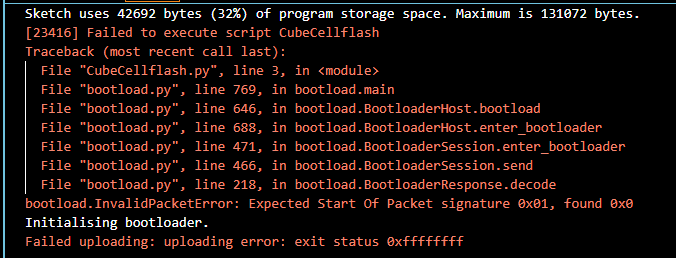
I know this has been talked about but I’m having an issue accessing the boot loader on my cubecell custom board. I’ve already read this forum post to no solution that worked for me: CubeCell Module + Custom PCB + How to Access Bootloader . Can anyone tell me where I’m going wrong? This is the error I’m getting:
image
Similar to the linked posts error messages but the solutions aren’t working. i followed the arduino recommended circuit on the heltec page here https://resource.heltec.cn/download/CubeCell/HTCC-AM01_V2/HTCC-AM01_Reference_Design(Arduino).pdf
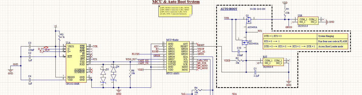
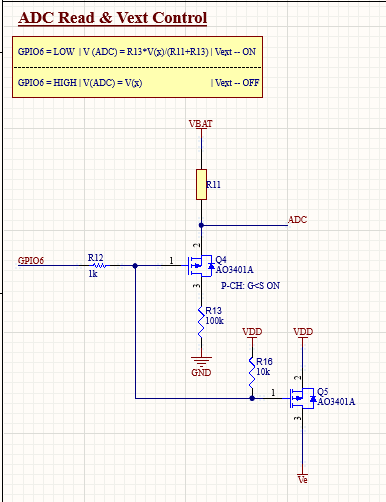
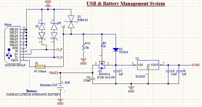
This is my circuitry:


image
I’d appreciate some help. Thank you.

Hello,
Just wanted to share some updates on debugging the design.
My driver installation and usb-uart circuit seems good as a com port is recognized on my device.
Things I’ve tried:

  1. Pulling GPIO0 to ground on power up - this did not work unfortunately.
  2. Removed Resistor R1 image to keep gpio0 line from being pulled high - no dice.
  3. Doing the User press and hold, Reset press and release, then user release for uploading - did not work.
    Currently, I’m looking at my power lines and current usage with the Nordic PPK2 device.
  4. Using the PPK2 as a source meter supplying a steady 3.6 volts on the VBAT line, I’ve verified 3.28 VOUT from the 3.3V regulator going into the processor. Ve is 2V without flashing, I’m not sure if this is correct but I assume it has something to do with voltage from GPIO6 in that part of the circuit. When I plug in 5v USB power, the mosfet switching circuit is still outputting 3.3 Volts which is good. However, I do start reading 4 volts on the Q3-3 input (the VBAT line). Don’t know why that’s happening.
  5. In terms of current, when I power the device, no usb connection. I see average system current draw of around 20mA. However, for some reason when usb is plugged in as well, system current drops to 1mA. What does this mean? Furthermore, when I then disconnect usb, system current is average 4mA.
    Is there a step I’m missing for setting up the module? I installed the board package in arduino and that’s all i think you need to do right? thanks