CubeCell Module + Custom PCB + How to Access Bootloader

Hi fellas,

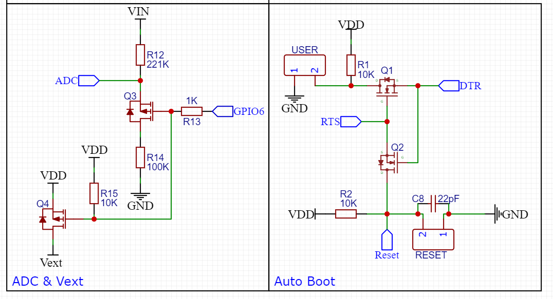
i got this problem here. I’ve made my own pcb by following the recommended design for arduino compatibility. I’ve tried to upload my sketch yesterday and its failed. i got the message:

[22616] Failed to execute script CubeCellflash
Initialising bootloader.
Traceback (most recent call last):
File “CubeCellflash.py”, line 3, in
File “bootload.py”, line 769, in bootload.main
File “bootload.py”, line 646, in bootload.BootloaderHost.bootload
File “bootload.py”, line 688, in bootload.BootloaderHost.enter_bootloader
File “bootload.py”, line 471, in bootload.BootloaderSession.enter_bootloader
File “bootload.py”, line 466, in bootload.BootloaderSession.send
File “bootload.py”, line 218, in bootload.BootloaderResponse.decode
bootload.InvalidPacketError: Expected Start Of Packet signature 0x01, found 0x80
bootload.InvalidPacketError: Expected Start Of Packet signature 0x01, found 0x80"

Anyone know what i’ve done wrong? If i had to guess i would say there is no bootloader?

There are 2 module versions, one with arduino bootloader and one without.
Where have you bought it?

Hi wasn! I ordered my modules from heltec directly.

So, if there is no bootloader iam screwed i guess. Or is it possible to get the bootloader flashed by my own?
Is there someone who got the cubecell running by using the Keil IDE?

I have some modules here on my own pcbs
And they are running fine but i use vscode

How are you compiling the code?

The version i got from the heltec shop has no bootloader?
I have a few cubecell boards here and wrote the sketch for my purpose with the arduino IDE. I thought it would be just as easy with the modules.

Your modules have also no bootloader?

Thats weird, my modules are labeled with “Arduino-Compatible”. Maybe i was just unlucky with this one and i should grab a another module

Do you have build it the reset circuit?
If not you have to tie the gpio0 pin to gnd when applying power to activate the bootloader

Yes, of course i did. I append my schematics (easyeda), maybe there is a mistake i dont see.

finally it worked.

I thought the Reset-Button in the recommended design were a Normally-Open-Button, because it looks like one. In my pcb design it is just 2x-pin-header. I put a jumper on it and the module got flashed.

Love it. Thanks a lot wasn!

Edit:
Did some research now and it seems i were right, it is a NO-Button. Now i’m completely confused

It counts that it is working now.
Have fun with the cubecell range of products

I thought GPIO0 had to be taken to ground to make the bootloader work? Or are there two methods, one with USR/RESET and one with GPIO0? (I seem to remember this from a data sheet somewhere, with timing diagrams)

@wasn you pointedthis out here.

I have a very simple (too simple, it turned out) breakout board for the module, and I can get the boot loader up and it programmed sometimes. When it’s in-circuit it seems to fail to program due to a brownout or something – I’ve been a bit busy but back looking at this now.

I am thinking of respinning my breakout board with a header of GPIO0, 3v3, GND, RXD. TXD (and maybe another GND just to make taking GPIO0 low easier, and use a 6pin header). If anyone has an existing breakout-board layout for something similar I’d be keen to see it - I just wanted a small board with no regulator/charger/LED.

Ah wow, there’s some great stuff on the read-the-docs site about the order of ops, and recommended circuits, I should follow that on my new board, somehow (don’t really want buttons though).

I have to pull GPIO0 to GND in my case until the IDE starts with the sketch upload. So, that means, my auto boot circuit (USER+RESET method) does not work for some reason :frowning:

Same here. On the dev board plus I have to.
Connect Serial-to-USB module’s Vcc, GND, Rx and Tx. Then I plug it into my computer.
Next I

  1. Press and hold USER Button
  2. Press and Release RESET Button
  3. While still holding down the USER Button, program in my code
  4. Only after the programming is released do I then release the USER button

I am using platformIO, arduino framework.

1 Like

You can try like this:

  1. Press and hold USER Button
  2. Press and release RESET Button
  3. Release USER Button
    (So far, it has entered the Bootloader under normal circumstances)
  4. Compile and download the code

Not sure if someone over here is still looking for a solution to this but I though I would share what I did.

In a newer version of the HTCC-AM01 Recommend hardware design document, capacitor C10 was added. If you add this capacitor and you also remove pull-up resistor R1, you should be able to program the module without doing any button sequence. In the schematic of the HTCC-AB01, you can see that the pull-up resistor is not mounted (NC).

image

hi,

Thanks for your share. I want to add a little information.

Please note that the GPIO connected to the AM01 and AB01 USER buttons are not the same.

please refer the pictures:

AB01:

%E5%9B%BE%E7%89%87

AM01:

BTW, GPIO0 cannot be pulled to the end for a long time, because when GPIO0 is low, the MCU will enter bootloader mode.

I am having a related problem uploading to the AB02 model CubeCell. The sketch I have loaded spends almost all of its time in sleep mode (MCU frozen, LoRa 1262 running). Time after time the Bootloader fails to initialize; eventually it works.

  1. Is this a sign of an issue with the implementation of the CubeCellFlash.exe?
  2. To avert the problem, I tried adding some of my own code that runs when USER is pressed and exits lowPowerHandler. Still same issue.

I have experienced this same problem with a CubeCell V2 Dev-Board, using the Arduino IDE (2.0.2), and @jackyruth’s method worked for me. Thanks.