Hi,
Can someone tell me the power consumption of the Wireless Tracker in the respective states.
also can it be connected to a solar panel to charge the battery like the cubecell series?
Thankyou

Hi,
Can someone tell me the power consumption of the Wireless Tracker in the respective states.
also can it be connected to a solar panel to charge the battery like the cubecell series?
Thankyou
I have done some simple testing, but I haven’t dug in to real optimization yet.
Clocked at 80 MHz doing just about nothing (VExt disabled), about 35 mA.
GPS uses about 45 mA (requires VExt enabled). (So 35 + 45 mA @ 80 MHz)
In deepsleep, I measured 2.4 mA, which IMO is too high. So that’s when I started digging around, getting rid of all proprietary and Heltec libraries. And then I ended up working on a LoRaWAN stack that can be used instead of the LoRaWAN_APP, which I’m still working on. No promises, but will try to get back to this deepsleep power consumption today or tomorrow.
@bgoo022 got the redeeming words! Get rid of all the Heltec stuff and use proper libraries and I got it down to 18.5 uA without any effort 
Let me know if you require additional info.
I did a bit more investigation into the power consumption of the Wireless Tracker (v1.1).
As above, the deepsleep power consumption can go down to 18.5 uA, but here are some more numbers in active mode:
Empty sketch, Vext_Ctrl off:
 80MHz:  32.2 mA
240MHz:  44.5 mA

Empty sketch, Vext_Ctrl on:
 80MHz:  81.8 mA
240MHz:  95.0 mA

Sketch to display GPS info on display, ADC_Ctrl on:
 80MHz: 146.0 mA

Sketch to display GPS info on display, ADC_Ctrl off:
 80MHz: 107.0 mA
 40MHz:  88.0 mA (Serial1 baudrate = 230400)
 20MHz:  82.0 mA (Serial1 baudrate = 460800)

Sketch to get GPS info, display off, ADC_Ctrl off:
 80MHz:  94.5 mA
Some main takeaways:
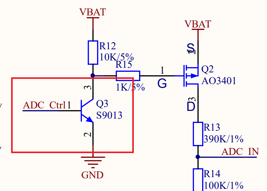
ADC_Ctrl circuit will easily reach max. current of GPIO2 pin when it is configured as OUTPUT.
Use INPUT_PULLUP and INPUT_PULLDOWN signals to reduce stress load on base-emitter circuit of Q3 transistor.
Quick measurement: using INPUT_PULLUP, readings are just as (if not a bit more) accurate, with power consumption minimal; the device is fluctuating a bit so hard to tell exactly but it would not be more than 0.5 mA and appears to be negligible most of the time. Thanks @Linar!
Not sure, but that was incorrect code either way. The 18.5 uA should be achievable on both v1.0 and v1.1, I expect. I am sure about v1.1 as that’s what I have.
@bns, I have a wireless tracker v1.1 and it’s (deep)sleeping at 1,4 mA. Could you tell me how you get 18.5uA? Thanks a lot
With that current consumption it looks like the radio isn’t put into sleep mode. If using RadioLib that would be radio.sleep(), or using the ‘raw’ SPI code that was posted on the forum earlier in another topic.
If only the LoRaWAN code in the example is used, the current when entering sleep mode is only 20uA.