
I can’t get I2C scan to discover a BME280 device. Does anyone have a sketch that works? What pins are active for SDA and SCL devices?
Wireless Stick V3
If you search the forum for “v3 i2c” you should find several threads discussing the use of the I2C bus on V3 modules. In my own case, I use pins 19 and 20—but others use a different pair—and define these when initialising the Wire object:
#define SDA 19
#define SCL 20
and
Wire.begin(SDA,SCL);
Thank you for your reply.
I have been trying everything to get this device to scan and reconize a BME280 device (that scans with an ESP32 Devkit V1)
But the board I’m using is the Heltec Wireless Stick V3 which has a dumb display attached which I don’t need.
You suggest pins 19 and 20 but I don’t see these on the pinout diagram. I see SCL (GPIO22) and SDA (GPIO21) which should work but they don’t.
I’m really starting to hate this board!
Are we looking at the same diagram…? Here’s the pinout diagram from the Heltec website:
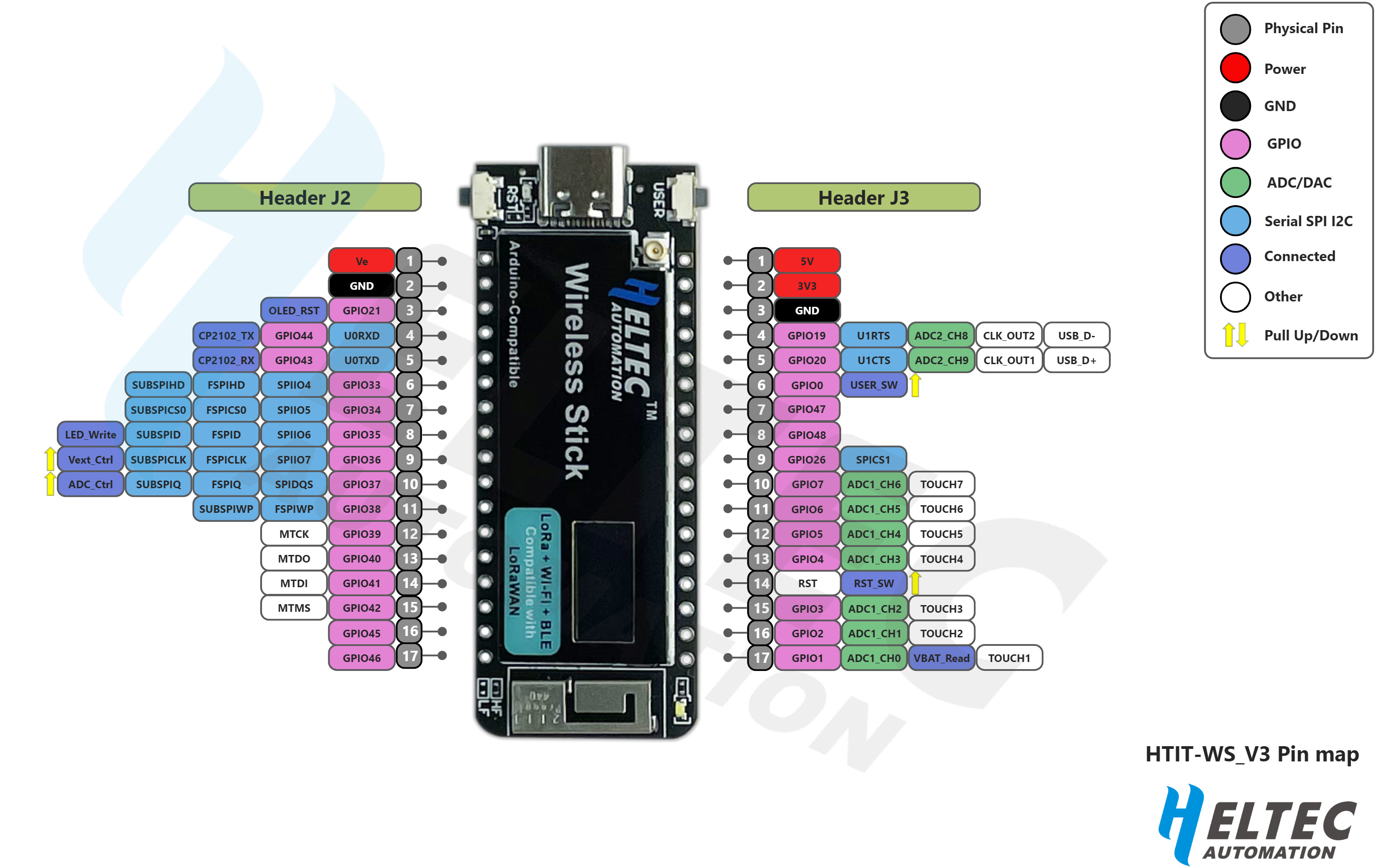
GPIO19 & GPIO20 are there on the right hand side, on pins 4 & 5 of the J3 Header…
Having said that, I don’t have a Wireless Stick, only a Wireless Stick Lite, but that shouldn’t make any difference in this case. Trying to use GPIO21 may, however, be problematic, as that’s the OLED_RST pin, and I can’t see a GPIO22 on this diagram…
Thank you! If I use those two pins I2C scanner sees my device.
My pinout diagram is different, but says it’s the same board
I’m not sure how this will impact the builtin display, but in my project I don’t really need it. I just need LoRa transmission of BME280 or BMP390 data.
Make sure you look at the V3 version! You linked the original version 
Got it! Thanks again!!!