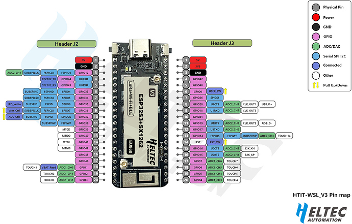
Wireless Stick Lite V3, I2C

I have a few WSL V3 boards and I am trying to get an INA260 board working with them for a Meshtastic node running at a solar powered site. I would like the INA260 to monitor the voltage and current at the site.

I have had the INA260, an adafruit 4226 breakout, working with a Lilygo T-Beam but for some reason it doesn’t seem to be plug and play with the WSL. The WSL is running the latest beta MeshTastic firmware and the SCL and SDA pins are 47/48 per the MeshTastic pinout.

https://meshtastic.org/docs/hardware/devices/heltec/

It doesn’t appear the I2C is working as I cant even get a simple .96 OLED screen to come to life.

Thoughts, suggestions?

According to the ESP32-S3 datasheet, under normal circumstances GPIO47 and GPIO48 are output only (see also this thread). I’m not familiar with Meshtastic or how you might configure alternate pins for the I2C bus but, one way or another, you probably need to try some different pins.

I am very much new to some of this type of configuration so I am learning as I go. I guess if those pins are only an output that would be an issue. I only “know” those pins are assigned SCL SDA because that is what is listed in the Meshtastic I2C definitions. I don’t know if it really makes a difference but I am speaking about the Wireless Stick Lite V3, which does appear to have a different pinout vs the ESP32-S3 talked about in the above mentioned thread. Or I am misunderstanding completely?

https://meshtastic.org/docs/hardware/devices/heltec/#meshtastic-i2c-definitions

I am 100% not bothered if I have to change them…but I assume that means some firmware editing which I have not done and would need to pointed in the right direction.

Doing some research I think I see what you are pointing out. The 47/48 pins on the pinout show them only as a GPIO, which I guess is just a glorified on/off type thing. I am assuming I would need it changed to one of the pins with the light blue “Serial SPI I2C” characteristics?

"I2C - Easiest and most expandable bus. Raspberry has two I2C buses, bus 0 and bus 1. Capable of expanding the Rpi to thousands of output ports. Programming is very easy.

SPI - Only 2 chip select lines so max number of devices is very limited. Bus is faster and can be driven over longer cable runs than I2C. Programming more difficult. Device selection very limited unless you are willing to solder SMD.

UART (RS-232) - Welcome to the 1970s. Lever shifters are a must. No intelligence at all. Pretty boring stuff actually.

GPIO - Good for turning on/off a few I-O ports. If all that is needed is control of a solid state relay or two for example, this is it. You could bit bang I2C or SPI but why would you when real I2C or SPI is available?"

And then finally I also noted in another post –

" Can GPIO be used for I2C?

An actual I2C bus is emulated using two GPIO pins (GPIO 6 and GPIO 7) . One pin is for data signals (SDA), and one pin is for clock signals (SCL). The software driver enables client software to operate as either a transmitter or receiver, depending on its function."

Maybe that is what is going on with the MeshTastic programming?

Hi there, I had a somewhat similar issue with another heltec board, connecting i2c to an ina3221 board. I could get it to communicate (poorly) only after lowering the SCL clock frequency and adding a strong pull-up resistor. My oscilloscope showed a not so pretty signal on the SDA line.

If you can, take a look at the signal in the data line.

Unfortunately I don’t have anyway to do that. Worst case scenario I can use a Lilygo Tbeam but I have the WSL and like the simplicity of it.

OK, several questions there. I have used both Wifi LoRa 32 V3 and WSL V3 boards and for the most part they work the same way insofar as relevant pins are actually broken out on the respective boards and available for use.

I don’t know how/why the Meshtastic people chose those pins, because my experience would suggest that they could never have worked. An I2C bus can, however, be configured on any two I/O pins that are not constrained by some other function (like a pin that must be held HIGH or LOW during boot etc.). The fact that the pin out diagram lists several functions for some pins and only one for others is not necessarily any indication of the capabilities of that pin with regard to I/O or its availability for use as an I2C bus. Strictly speaking, an output-only pin should be labelled GPO, not GPIO, but the only way I know to divine what can truely be done with any particular pin is to look at the [ESP32-S3] processor datasheet.

By default, all pins on the ESP32 are digital pins, which just send or receive a HIGH (3.3V) or LOW (0V) signal. ESP32 pins can, however, also all be coupled with an internal ADC to manage analog signals, although ‘conditions apply’.

Now, having said that, if a particular pin is used for a particular function on a particular board (in the above pin map, the pins with ‘purple box’ functions are an example), it may not be available for any other use without negative consequences.

Searching through the Meshtastic GitHub repository, I find the following:

https://github.com/meshtastic/firmware/blob/master/variants/heltec_wsl_v3/variant.h

which identifies the pins used for the I2C bus on the WSL V3 board. This file needs to be amended to identify the GPIOs that you want to use, or you could just try redefining the relevant parameters in your sketch, something like:

#define I2C_SCL 19
#define I2C_SDA 20

replacing the numbers by whatever GPIOs you ultimately choose to use.

2 Likes

Awesome sauce.

Thank you for taking the time to do research and answer questions! This is all very helpful.