Wireless Shell and Dev Board

I purchased a few Wireless Shell units along with the Dev Boards. Installed the Wireless Shell on the Dev Board and checked all the pins to ensure there were no shorts etc.

Checked that the USB drivers were installed, Installed the relevent board in to Arduino IDE as well as the examples and library.?

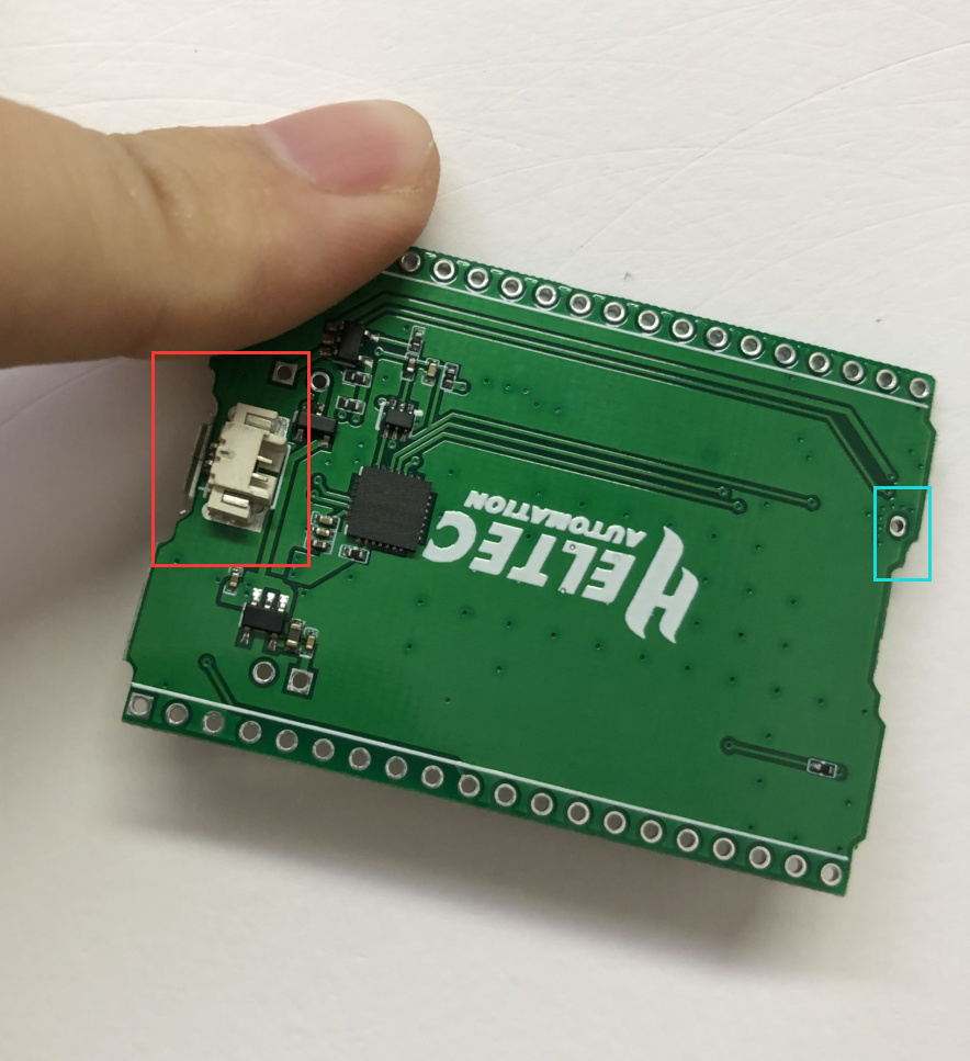
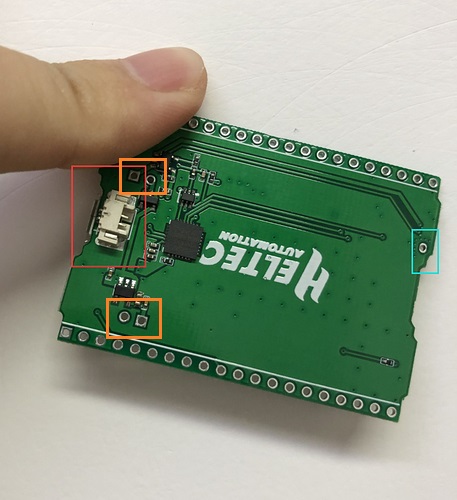
Connected the board and the white LED flashes really fast, Orange LED is really dim.
It created the USB device, Selected that as per the recomentadion. Selected WiFi Lora 32 and tried to program.

No response, Opend a serial connection and there seems to be no commujnications at all.

Any sugestions?

@vangalvin

Try to choose “Wireless Stick Lite” in Arduino IDE.

Found the issue :slight_smile:
The board did not have any details published and it turns out that the module is not powered on via the serial port. you need to jump the 3.3 pin in order to get power to the module.

So far its working great :slight_smile:

We will update some more documents about this board.

That would be awesome, There are still a couple of unusual things going on like the white LED flashing really fast. not sure how to change this or turn it off. and the proper way to connect power.

:slight_smile:

https://docs.heltec.cn/#/en/faq/heltec_esp_series_common_problem_summary?id=orange-led-blink-problem

Thanks for that information however the board I have is the Wireless Shell Test Bottom Board. Its the White LED that is blinking like mad. I assume this may be cause by the same thing?

@vangalvin Yes, the schematic of the bottom board is referred to this:

Great. Thanks. however on the top of the board there are what appears to be jumpers for a 3.3V connection and a BAT connection that is not shown in the circuit diagram. On the bottom of the board there is the battery connector Or what I assume is the battery connector.

There is also a pin connector for an antenna. is this connected to the 2.4Ghz radio or the LoRa radio and is this connected to the same line/pin as the ufl?

Completely correct!
The SH-1.25 socket in red box is for battery, and the hole in blue box is for WiFi / BLE antenna.

Anyway, both LoRa and WiFi have an IPEX socket.

3VandBatt

These are the connectors i am talking about. If i do not have a battery source and want to run the unit off USB power do i just put a jumper on the 3.3V line? and what is the Battery jumper connected to? Is that connected directly to the battery input or the regulated 5V output? or do you jumper this if a battery is installed?

Also if a battery is installed do you remove the jumper on the 3.3V pins?

At present my battery pack has not arrived for the test project so I have to run the unit directly from USB power.

Haha, I know you mean now. Connect your battery positive to this hole, battery negative to any GND pin.

This hole was left to measure the current of the battery. If your battery has an SH1.25-2 connector, need to keep both the two holes keep close.

1 Like

Pictures make things so much easier!
I see from the circut design the battery has a low power cutout, what is the drop off voltage? It looks like this means that I can do away with the BMS circut :slight_smile:

http://aosmd.com/pdfs/datasheet/AO3401.pdf

Anyway, it’s an auto switch system for USB and battery power source.

1 Like

Received my first lot of battires today so just wiring one up, also installed a divider on to pin 13 and connected it to the battery terminlal so I can keep a track of the voltage.