Buenas tardes,
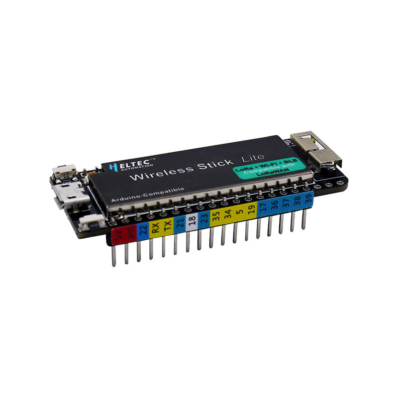
I have a wireless stick lite module.
I want to use spi to communicate a sensor without interrupting the sending of messages to ttn v3.
What do you think I can use to make this communication?
Thank you very much for your help

Buenas tardes,
I have a wireless stick lite module.
I want to use spi to communicate a sensor without interrupting the sending of messages to ttn v3.
What do you think I can use to make this communication?
Thank you very much for your help
You can use another set of SPI, you can refer to CubeCell’s SPI(https://github.com/HelTecAutomation/CubeCell-Arduino/tree/master/cores/asr650x/SPI) to start the second set of SPI.
ESP32’s SPI pins can use any GPIO, and you can select free GPIO pins as SPI pins.
Thank you very much for your answer, will you have a small example for the pin declaration to use any pin for the SPI in the wireless stick lite?
I have tried but have no signal response
I want to have data from an RC522 card but I have no data, I have looked everywhere but I have had no response
/* The ESP32 has four SPi buses, however as of right now only two of
// Define ALTERNATE_PINS to use non-standard GPIO pins for SPI bus
#ifdef ALTERNATE_PINS
#define VSPI_MISO 2
#define VSPI_MOSI 4
#define VSPI_SCLK 0
#define VSPI_SS 33
#define HSPI_MISO 26
#define HSPI_MOSI 27
#define HSPI_SCLK 25
#define HSPI_SS 32
#else
#define VSPI_MISO MISO
#define VSPI_MOSI MOSI
#define VSPI_SCLK SCK
#define VSPI_SS SS
#define HSPI_MISO 12
#define HSPI_MOSI 13
#define HSPI_SCLK 14
#define HSPI_SS 15
#endif
static const int spiClk = 1000000; // 1 MHz
//uninitalised pointers to SPI objects
SPIClass * vspi = NULL;
SPIClass * hspi = NULL;
void setup() {
//initialise two instances of the SPIClass attached to VSPI and HSPI respectively
vspi = new SPIClass(VSPI);
hspi = new SPIClass(HSPI);
//clock miso mosi ss
#ifndef ALTERNATE_PINS
//initialise vspi with default pins
//SCLK = 18, MISO = 19, MOSI = 23, SS = 5
vspi->begin();
#else
//alternatively route through GPIO pins of your choice
vspi->begin(VSPI_SCLK, VSPI_MISO, VSPI_MOSI, VSPI_SS); //SCLK, MISO, MOSI, SS
#endif
#ifndef ALTERNATE_PINS
//initialise hspi with default pins
//SCLK = 14, MISO = 12, MOSI = 13, SS = 15
hspi->begin();
#else
//alternatively route through GPIO pins
hspi->begin(HSPI_SCLK, HSPI_MISO, HSPI_MOSI, HSPI_SS); //SCLK, MISO, MOSI, SS
#endif
//set up slave select pins as outputs as the Arduino API
//doesn’t handle automatically pulling SS low
pinMode(VSPI_SS, OUTPUT); //VSPI SS
pinMode(HSPI_SS, OUTPUT); //HSPI SS
}
// the loop function runs over and over again until power down or reset
void loop() {
//use the SPI buses
vspiCommand();
hspiCommand();
delay(100);
}
void vspiCommand() {
byte data = 0b01010101; // junk data to illustrate usage
//use it as you would the regular arduino SPI API
vspi->beginTransaction(SPISettings(spiClk, MSBFIRST, SPI_MODE0));
digitalWrite(VSPI_SS, LOW); //pull SS slow to prep other end for transfer
vspi->transfer(data);
digitalWrite(VSPI_SS, HIGH); //pull ss high to signify end of data transfer
vspi->endTransaction();
}
void hspiCommand() {
byte stuff = 0b11001100;
hspi->beginTransaction(SPISettings(spiClk, MSBFIRST, SPI_MODE0));
digitalWrite(HSPI_SS, LOW);
hspi->transfer(stuff);
digitalWrite(HSPI_SS, HIGH);
hspi->endTransaction();
}