This is a simple code created by looking at the post above.
#include <Arduino.h>
#define VBAT_PIN 1
#define ADC_CTRL_PIN 37
#define BATTERY_SAMPLES 20
void VBAT_Init() {
pinMode(VBAT_PIN, INPUT);
pinMode(ADC_CTRL_PIN, OUTPUT);
}
float readBattVoltage() {
digitalWrite(ADC_CTRL_PIN, LOW);
uint32_t raw = 0;
for (int i = 0; i < BATTERY_SAMPLES; i++) {
raw += analogRead(VBAT_PIN);
}
raw = raw / BATTERY_SAMPLES;
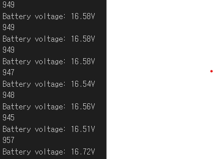
Serial.println(raw);
digitalWrite(ADC_CTRL_PIN, HIGH);
return 5.42 * (3.3 / 1024.0) * raw;
}
void setup() {
Serial.begin(9600);
VBAT_Init();
}
void loop() {
float voltage = readBattVoltage();
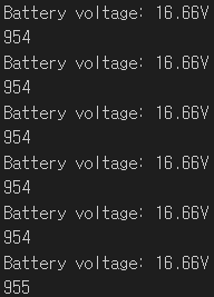
Serial.println("Battery voltage: " + String(voltage) + "V");
delay(1000);
}
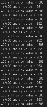
Only Type C USB
Serial monitor Output(GPIO1,the battery voltage.)
 Serial monitor Output(GPIO1,the battery voltage.)
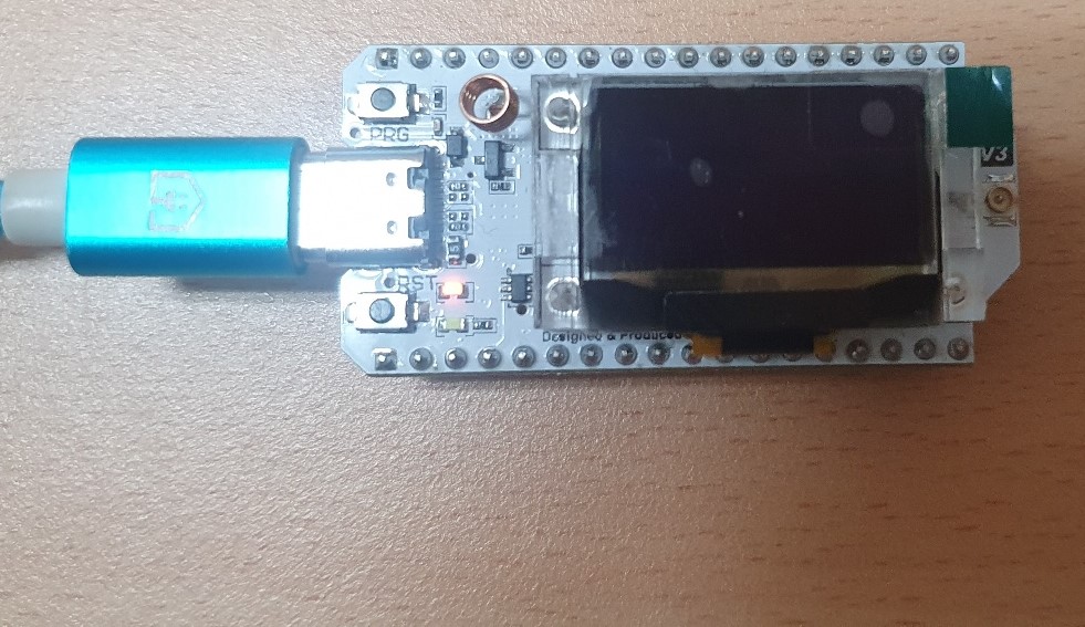
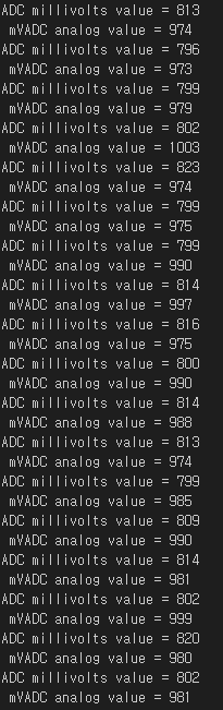
Type C USB +3.7 V Lithium-ion Battery
Serial monitorOutput(GPIO1,the battery voltage.)
 Serial monitorOutput(GPIO1,the battery voltage.)
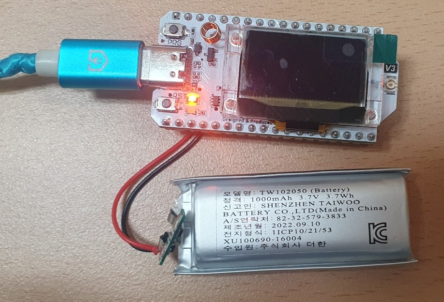
The article describes a battery voltage measurement code for a device called Stick Lite V3. The code takes multiple ADC readings of the battery voltage, averages the readings, and calculates the final voltage measurement using a constant factor of 5.42 * (3.3 / 1024.0). The code also outputs the results to the serial monitor.
The author is now looking to modify the code for the WiFi LoRa32 V3 device, and wants to change the constant factor used in the voltage measurement calculation. The author found the voltage measurement formula in the datasheet for the WiFi LoRa32 V3, which uses resistors R1 = 390 and R2 = 100.
(https://heltec.org/project/wifi-lora-32-v3/)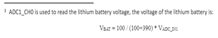
The author is asking for help to write a code for measuring voltage on the LoRa32V3 device, using the information from the datasheet.