Thank you both for the additional information regarding the pins! Okay, then I will try the test without board and the simple blinky test, and after I will try blinking the LED with a different GPIO. I’ll just have to see how I’ll connect my sensors in the future, as I currently have them on GPIOs 2 to 7 – and there may be even more at one point. (yes, combination sensors exist but those are usually from high-end manufacturers and cost upwards of 1,000€ (asked for quotes from some) so that’s not a possibility).
WiFi LoRa 32 V3: Send sensor data via LoRa, then go back to deep sleep
I do not know what sensors you are currently using, but a lot of sensors offer an I2C interface. And you can connect multiple I2C sensors to the same bus, i.e., to the same GPIO pins. One requirement here is that they need to have different addresses. Then you can read them individually. The OneWire (used for your DS18B20) bus also allows to connect multiple devices (sensors) to the same OneWire bus.
If you want to describe your hardware setup in your PhD thesis, you already have an outline for a small chapter for your thesis: Compare the different possibilities to connect sensors: Analog sensors which need an ADC, digital sensors with proprietary interfaces, serial connections (TTL, RS-232, RS-485, RS-422, …), I2C, OneWire, SPI and so on. Each variant has advantages and drawbacks.
Thank you for this information!
Regarding the tests that were done yesterday, my dad did a run with just the basic setup you had suggested (which I had drawn the diagram for), and that caused the LED to be off when connecting En and Vin while it was on when they were not connected. Using the board without the controller had the correct behavior. Just wanted to clarify that.
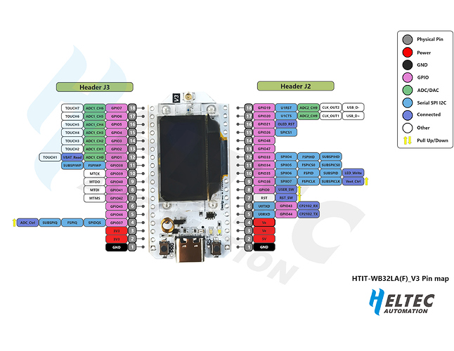
Here’s a quick reference as to which pins can do what and which ones to avoid - 46 definitely being one of them, see pink box bottom left:
This specifically covers the version of the ESP32 that is on the v3 board but is for the generic module, it’s not specific to Heltec.
This, on the other hand, is from Heltec and in keeping with policy, lacks the sort of details that cause exactly these sorts of problem - I’d give it a 50/50 chance that using pin 46 could have happened to me as I’ve notes on the startup pins for earlier modules and it wouldn’t have occurred to me that Espressif would go and use another one!
Thanks, that’s a nice resource and visualization! From the Heltec pin layout you’d guess it’s a GPIO pin with no other functionalities, what a way to mislead developers.  I had already said that I will retry tests on another pin, and 47/48 look nice and safe.
Got to my desk, took out the regulator and my WSL V3; here is the setup and code that should get you there:
Vin <--> device 3V3 (or in your full setup: Sunny Buddy 3.7V)
Gnd <--> any Ground
5V <--> LED with the cathode to Ground through resistor (or in your full setup: to your sensors)
En <--|--> GPIO47
      |--> resistor <--> any Ground
/*
  Blink - deepsleep
*/
#define VReg 47
#define TIME_TO_SLEEP 10

void setup() {
  pinMode(VReg, OUTPUT);
  digitalWrite(VReg, HIGH);   // turn the LED on (HIGH is the voltage level)
  delay(5000);                // wait for a second
  // don't need to specifically write to LOW as pin state is lost on deepsleep
  esp_sleep_enable_timer_wakeup(TIME_TO_SLEEP * 1000000ULL);
  esp_deep_sleep_start();
}

void loop() {
}
With this setup, my LED is off by default (during deepsleep), and in the code you must set the driving pin (47 works fine) to HIGH. So it should work as you’d hope it to work!
And on the WSL V3, GPIO 45 and 46 appear to work just as well. Side note that I didn’t care enough to find a >=10k resistor and did this on a 330Ohm pull-down resistor, which would result in a (small) power leak. If it works on a smaller resistor, you could try some larger values to see if it still works just as well.
Thank you, I will try this on Friday when I’m back home!
The long awaited update…
So, using GPIO47 magically solved all issues. The LED blinks perfectly now, regardless of whether I use a super basic blinky code or the one with deep sleep @bns provided. I will do a test with my sensors and report how that worked. If that works nicely, I’ll use the sending code where I’ll measure and send data every 60 minutes … if there are rejoins, I’ll end that experiment immediately and go back to testing without sending. Wish me luck! (believe me I need it, I’m quite the unlucky person)
Latest Update
The sensors are now OFF during sleep. I tried a cycle of 1 minute for quick tests.
Here’s the code:
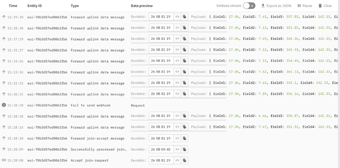
Here’s the result:
No annoying re-joins, data is being sent nicely every minute (sometimes every two but let’s cut the system some slack lol). Will set the duty cycle to 60 minutes and power via USB, tomorrow I will repeat the sending every hour part with battery power as the battery should be fully loaded by then.
Let’s see if turning the sensors off will improve the total runtime on battery.
Woohoo, time for a party!!
I fear not.
I tried sending every 60 minutes, powered by USB, then the re-joining every minute happened again. So I set it back to sending every minute, but there I still have a problem with the re-joins and values being completely wrong again.
The values are correct again but the issue with the re-joins is still there. I don’t understand why … can’t it just work like it’s supposed to … 
Just nipping to the wine cellar to get out a bottle of Bubbly 
Let the party start! 

This rejoin loop was down to the board resetting due to power supply issues. The quality of USB leads varies so it may be worth trying a different one.
Or the connector may have got wobbly like the LoRa32 v2 I had on the sofa last night - every time I pressed the PRG button to push to send the power disconnected. But the 426 error I was getting was entirely @bns’s fault.
Yeah, something strange is certainly going on. I uploaded a code without sending, let that run for a few minutes, then uploaded the code with sending again. The result:
- one re-join when the code was first executed (normal)
- then 3 data packages were sent
- at the time the 4th should have been sent, I get a re-join
- then 2 packages were sent
- re-join with immediate package after
- repeat the last two steps
I’ll check if I have another USB to USB-C cable lying around and test if that does something to improve things. Otherwise, I also have a second board that I could test, just to be safe.
Going onto thin ice there boomer!
Sounds like it’s working but just some kinks in the cable.
I tried the old board with the old cable, then with the new cable, then I tried a new board with the old cable, then also with the new cable, but the results remain the same. Two packets go through, then the next re-join comes.
For testing, I set the duty cycle to 5 minutes now. Will eat dinner, and check afterwards if that lead to any improvements with the re-joins. Even if it still re-joins on every third transmission, then it’s still better to get a re-join every 15 minutes than every 3 minutes 
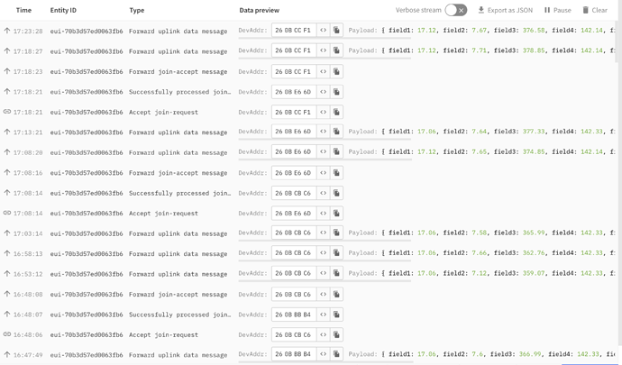
The result:
I still get a re-join on every third transmission.
Anyone have an idea what could be the reason?
So the circuit appears to be working fine - you can now start worrying if your code actually handles resetting sensors due to power-off etc.
First test would be a bit smaller interval (say 60s) and have it blink an LED during wake, and let your device send some dummy payload (say random value between 0 and 10) through LoRaWAN. If that also fails, there may still be something in the circuit. If that works, it’ll be much more likely that a sensor “crashes” and doesn’t send an ACK to your device causing that to crash or so.
Okay, I will try that tomorrow. Maybe I’ll even start by plugging off all sensors (then usually some nonsense data gets send to TTN) and then plugging them back on one by one, that might help me assess fastest which specific sensors might cause problems (I fear it’s the TDS and turbidity sensors).
I was looking at your code on github, @jsteiwer. While I really appreciate that the code in your loop() follows an FSM (finite state machine) approach, it is very hard to debug since the transitions to the next state are sometimes triggered by your own code, sometimes by code from the Heltec LoRaWAN implementation. Could it be that you really sometimes end up in the wrong state and re-join for this reason? To fully understand what is happening in your program, you need to at least additionally consider what happens in LoRaWan_App.cpp. On the other hand, the code you used as a base for your program is essentially the original Heltec LoRaWAN example. But I also do not fully understand what logic they are following in their implementation, especially w.r.t. the state transitions, for example, when their timer expires. And how the timeout for this timer and going to sleep are exactly related.
I really do not want to dive further into the Heltec code, sorry.
I have done runs in the past with the code where the data was sent for +7 hours every 30 minutes without a single re-join, and I did a test earlier today where for sending every minute, for a duration of 15 minutes, there was also no re-join.
I tried to power the system with a USB phone charger, and then suddenly got weird behavior. However, this behavior persists even using a different cable and board. I’ll try Steven’s suggestion tomorrow, maybe it’s just a sensor doing whatever again. That Heltec code works for countless people, it would be odd if it just didn’t work for me (or maybe my bad luck has gotten even worse, who knows).
The only digital sensor you use is the DS18B20. All other sensors just provide analog data. When one of the analog sensors would misbehave, all that would happen would be that you get nonsense data. This would not change the progress in your program in any way, shape or form. So there are three possibilities:
- The OneWire implementation might not work correctly with your deep sleep solution.
- The circuit might somehow still be buggy. Breadboards are notorious for making bad connections from time to time.
- Your code might still have some issues.
By decoding some smoke signals I noticed that @nmcc has been working on improving the RadioLib examples - maybe he’s able to supply an easy example that could replace the stupid Heltec FSM without needing to change much of the code but giving actual control over what happens in the loop.


