
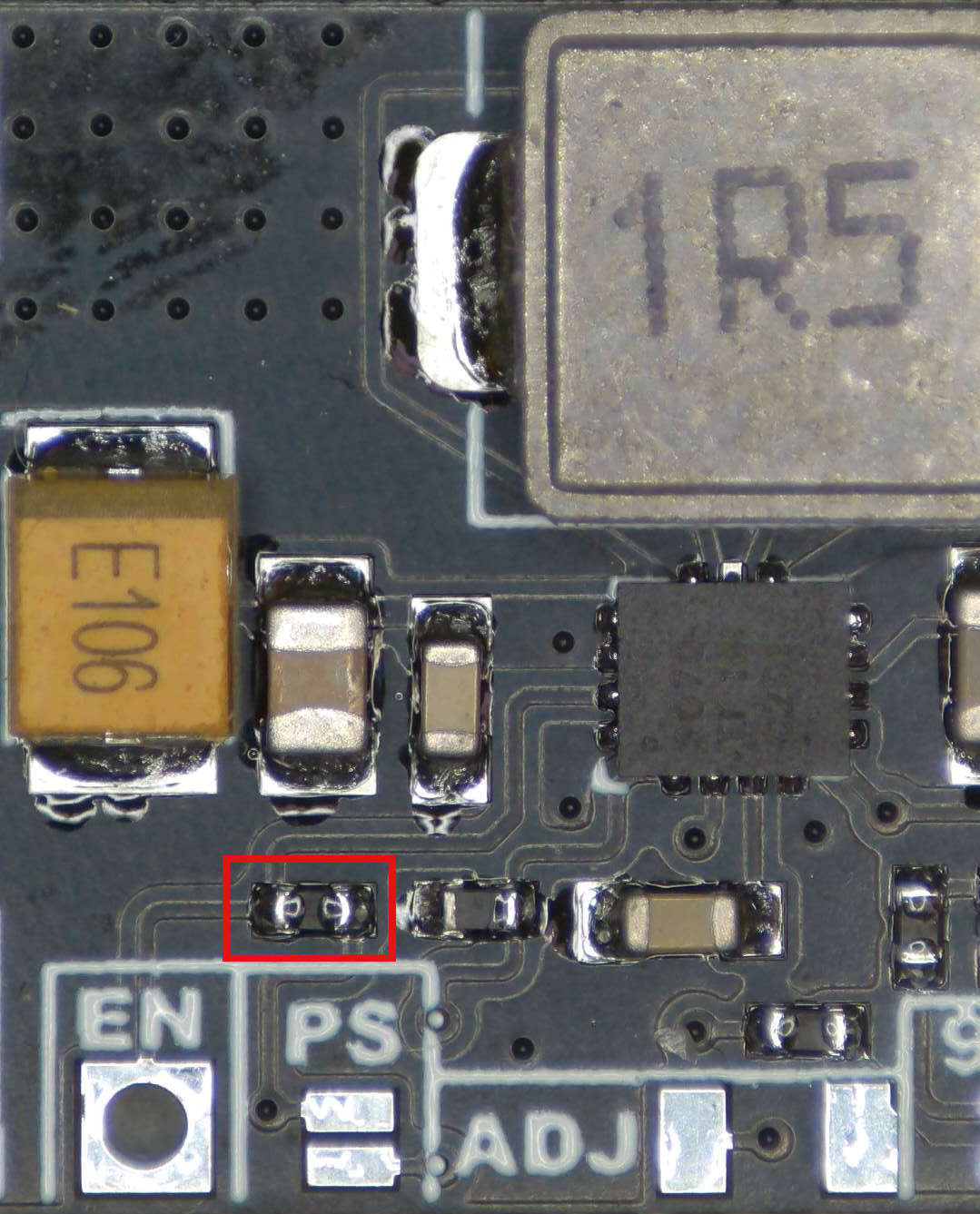
I do not want to confuse @jsteiwer, so this is more for @bns: The buck-boost I linked uses a TPS63070 or a clone of this chip. The datasheet of the TPS63070 states that the enable pin must not be left floating. So, the board needs to use a pull-up resistor. I have some of these cheap modules in my lab. If I wanted to use these in low standby power applications, I would simply remove the pull-up resistor and connect the ENABLE pin (of the module) to GND via a high-value resistor. An additional connection to the ENABLE pin could then be used to switch the module on and off. So, DIY off-by-default is very easy.
EDIT: In case you want to do this with exactly this model: Remove the resistor marked in red. It is 10 kOhm. But this module uses a tantalum input capacitor, it might go up in flames.
 during deep sleep (so for 60sec) and briefly turns off
  when the board wakes up, and then goes back on
  )
)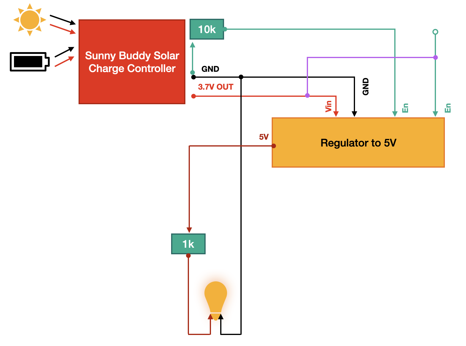
 , looks good. And yes, the end of the violet wire you should touch to VIN can then be connected to a GPIO pin. When this GPIO is set to LOW, the LED should be off, when the GPIO is high, it should be on. For safety reasons, you can later also try to include a lower value resistor between the GPIO and the EN pin. It should even work with a value of 10 to 20 kOhm, but this is something to worry about later, once this basic setup in your diagram works as expected.
 Will let you know if it worked!