WiFi LoRa 32 V3: Send sensor data via LoRa, then go back to deep sleep

They haven’t tested a few hundred potential boards, so I wouldn’t worry about the absence of your particular board - Arduino eco system is mostly compatible across the board at a basic level like this.

If it works OK on USB power but not battery, you are probably suffering from power droop where the sensor is not getting enough volts &/or current. How are you powering on battery?

I have a breadboard where I have my battery, sensors, and controller board connected to. I wanted to check if the issue might be on the technical side, so I measured the voltage.

It appears that the issue might have been caused by the water just being “too clean” (we have very hard water here but otherwise it’s free of salts or pollutants). At the 5V pin of the sensor converter board, I measured 5V, and at the analog pin I measured 0.2V for tap water. I then created a salty solution (literally smells like sea water :woozy_face:) and put the sensor in there, that got me 3.24V on the analog pin (max output of the sensor is 3.4V).

Below you can find an image that shows the last measured value of my sensor (when I put it in the salty solution) with the spike in the measurements.

So it seems that my setup is okay, the sensor is getting full power, the code is correct, and the issue was entirely because of the water not having enough ions. I hope this was the only reason and that there isn’t some hidden issue somewhere left that gets me at a later point.

Thank you for taking your time to reply!


Sometimes, the EC will still only show 0.00, even when in the saline solution. I don’t know if this is because the salt fell out to the bottom or if it’s a sensor issue – I know that this sensor is more lab grade which means technically it’s not supposed to be in the water all the time, but this behavior is still odd.

Next week (KW4) we will supposedly have positive temperatures even at night, then I should try the sensor suite in one of our ponds, maybe there the EC won’t fall to 0.00 – in the meantime, I’m happy for any ideas why I might get these weird results.

@nmcc @colinmcmahon @bns

Sorry to tag you this directly, but I tested the code again, this time by powering the sensors via the Ve pin.

The setup is like this:
The Heltec board is powered via USB-C cable from the Laptop (-> I face the same issue when powering with a battery), and the outputs of the sensors are connected to the pins on the Heltec board. The GND and Ve pin of the Heltec board are connected to a step-up converter that increases the 3.3V input of the board to an output of 5V to supply the sensors. The GND and 5V output connections of the step-up are connected to a breadboard where the GND and 5V pins of the sensors are plugged into.

Now, I face the following problem: The board does not go into deep sleep at all.
Right after the display tells me “Into deep sleep in 2s”, the screen turns black for maybe a second before trying to join TTN again. The sensors also remain powered on the whole time, while I had hoped that powering them with Ve would mean they also turn off during deep sleep.

Even when I only power the board without any sensors, the behavior remains.

I am still using the same code as last time, so technically this should not be happening.

I honestly have no idea why this is happening; regardless of how I power the device, it connects to TTN every few seconds instead of going into deep sleep.

If any of you have an idea what the issue might be, I’d be more than willing to test your suggestions. Thank you already in advance!

This tells us it’s not the sensors, so that helps narrow it down.

Deep down, under the grumpy old engineer who is a pedant for the scientific process, I’m a pussy cat with a soft spot for those the try. So please excuse me if I’m a bit blunt, it’s just me.

When you say “the same code”, the thread says that you were using HeltecV3_LoRaWAN_deepSleep_allSensors_5V.ino but are now using workingCode.ino. I can see that you’ve turned off the EC sensor but still have some of the processing code around line 280 which shouldn’t make any difference but none the less, you aren’t using the same code. So it may be worth using your HeltecV3_LoRaWAN_deepSleep_allSensors_5V.ino code as a quick sanity test.

I’d suspect that the board is resetting - which you can verify via the serial log - @bns loves big logs, he cannot lie, so if you do post one, please use the </> tool to format it.

I have a water quality rig, as an IoT peep commissioned by a client, I’m not a marine bod. It sports some very fancy Ion Specific Membrane sensors (Nitrates & Ammonia) along with most of the ones you have. I wanted to make an autonomous raft to survey a very large lake last summer (denied! no budget), so you have my attention & admiration.

Let me get my WiFi LoRa 32 V3 out the office and I can have a proper poke at the code. But first it’s time for me to cook supper.

1 Like

Shush you, @jsteiwer: he’s leaving out the fact that he supplied me with a 400MB log, generated in 16 hours by crashing a device 30,000 times. Which was partially my fault, before he starts complaining about that.

1 Like

Thank you very much!

Okay, so I uploaded the Heltec example LoRaWAN code to my board to reset it, then I uploaded workingCode.ino again to see what that does. Without attaching any sensors and just powering the board via USB, the code was executed properly with the board going into deep sleep. Next, while in deep sleep, I plugged all the sensors back on powering them with GND and 5V on the Heltec board. Unfortunately, just 5 minutes before the next data transmission (I had unfortunately kept the deep sleep time at 30 minutes instead of setting it lower for testing purposes, stupid me), the Polish construction crew tasked with setting up a fibre optic cable cut through our current connection cable. :roll_eyes: You know, despite my dad telling them in both German and English (unfortunately they understood neither) that they cannot dig there and there being like a thick yellow band on top that says “careful! cable” …

Anyways, since my LoRa Gateway is connected to my home internet connection, I currently cannot test anything with it. Sure, I could try resetting that thing to my mobile hotspot but I fear that it will cause more issues than fixing them. The construction crew alerted their bosses to breaking our cable, so hopefully, someone will come tomorrow (it’s a Saturday so technically still a working day) and fix that for us, otherwise I’ll be quite mad because I wanted to get this running smoothly and collecting nice data as I’m presenting my work next week and it would have been nice to show some real-time values on my laptop. – sighs –

If you could test the code and tell me what it does for you, I’d appreciate that a lot. I hope supper was delicious.

@bns So I don’t have a lengthy log file but I will just add the snippet I got when the board was not entering deep sleep; that snippet repeated continuously so I think even with just a short log it might tell you a lot already.

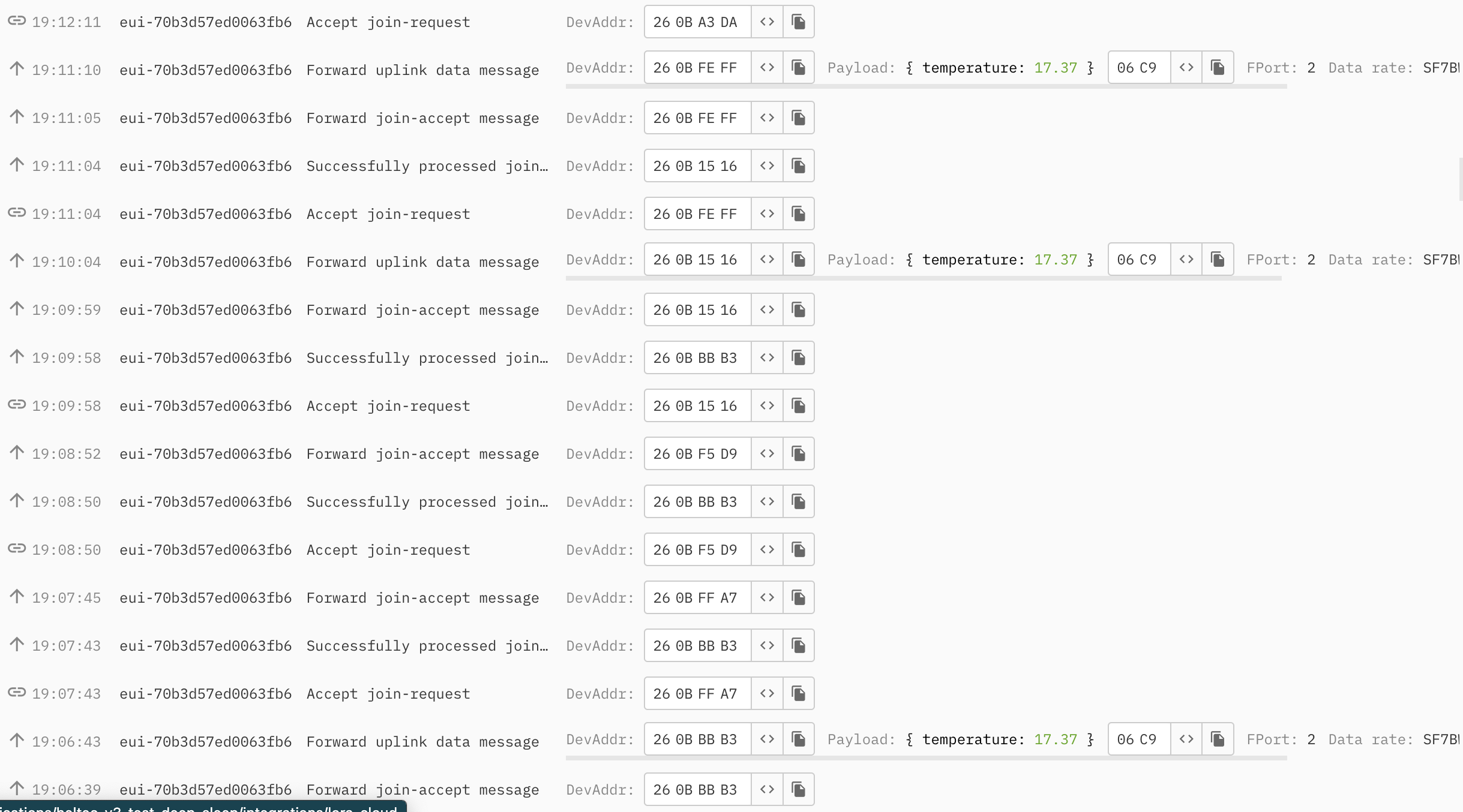
15:09:53.974 -> joining...
15:09:59.144 -> joined
15:09:59.904 -> confirmed uplink sending ...
15:10:14.009 -> received unconfirmed downlink: rssi = -74, snr = 15, datarate = 5
15:10:16.052 -> Guru Meditation Error: Core  1 panic'ed (StoreProhibited). Exception was unhandled.
15:10:16.052 -> 
15:10:16.052 -> Core  1 register dump:
15:10:16.052 -> PC      : 0x400570e8  PS      : 0x00060430  A0      : 0x82002cdc  A1      : 0x3fce2ed0  
15:10:16.154 -> A2      : 0x00000000  A3      : 0x00000000  A4      : 0x00000400  A5      : 0x00000000  
15:10:16.154 -> A6      : 0x3fce3e84  A7      : 0x00000040  A8      : 0x60023000  A9      : 0x60023040  
15:10:16.189 -> A10     : 0x15968d40  A11     : 0x000fffff  A12     : 0x00000000  A13     : 0x00000001  
15:10:16.189 -> A14     : 0x00060420  A15     : 0x00000001  SAR     : 0x0000000a  EXCCAUSE: 0x0000001d  
15:10:16.189 -> EXCVADDR: 0x00000000  LBEG    : 0x400570e8  LEND    : 0x400570f3  LCOUNT  : 0x0000003f  
15:10:16.189 -> 
15:10:16.189 -> 
15:10:16.189 -> Backtrace:0x400570e5:0x3fce2ed0 |<-CORRUPTED
15:10:16.189 -> 
15:10:16.189 -> 
15:10:16.189 -> 
15:10:16.189 -> 
15:10:16.189 -> ELF file SHA256: 0000000000000000
15:10:16.189 -> 
15:10:16.189 -> Rebooting...
15:10:16.189 -> ESP-ROM:esp32s3-20210327
15:10:16.189 -> Build:Mar 27 2021
15:10:16.189 -> rst:0xc (RTC_SW_CPU_RST),boot:0x8 (SPI_FAST_FLASH_BOOT)
15:10:16.189 -> Saved PC:0x4202f3e6
15:10:16.189 -> SPIWP:0xee
15:10:16.189 -> mode:DIO, clock div:1
15:10:16.189 -> load:0x3fce3808,len:0x43c
15:10:16.189 -> load:0x403c9700,len:0xbec
15:10:16.189 -> load:0x403cc700,len:0x2a3c
15:10:16.189 -> SHA-256 comparison failed:
15:10:16.189 -> Calculated: dcde8d8a4817d9bf5d5d69a7247667264e4e10ac7493514868b61f5aa6146539
15:10:16.189 -> Expected: ffffffffffffffffffffffffffffffffffffffffffffffffffffffffffffffff
15:10:16.189 -> Attempting to boot anyway...
15:10:16.189 -> entry 0x403c98d8
15:10:16.380 -> Start
15:10:16.414 -> Setup fertig
15:10:16.643 -> 
15:10:16.643 -> LoRaWAN EU868 Class A start!
15:10:16.643 -> 
15:10:16.643 -> +OTAA=1
15:10:16.643 -> +Class=A
15:10:16.643 -> +ADR=1
15:10:16.643 -> +IsTxConfirmed=1
15:10:16.643 -> +AppPort=2
15:10:16.643 -> +DutyCycle=300000
15:10:16.643 -> +ConfirmedNbTrials=8
15:10:16.643 -> +ChMask=0000000000000000000000FF
15:10:16.643 -> +DevEui=[my-dev-eui-here](For OTAA Mode)
15:10:16.643 -> +AppEui=[my-app-eui-here](For OTAA Mode)
15:10:16.677 -> +AppKey=[my-app-key-here](For OTAA Mode)
15:10:16.677 -> +NwkSKey=00000000000000000000000000000000(For ABP Mode)
15:10:16.677 -> +AppSKey=00000000000000000000000000000000(For ABP Mode)
15:10:16.677 -> +DevAddr=00000000(For ABP Mode)

After that, the log repeats with joining.... What I never experienced before is all that stuff from Guru Meditation Error: Core 1 panic'ed (StoreProhibited). Exception was unhandled. to ELF file SHA256: 0000000000000000 and I think also that SHA-256 comparison failed: line; everything else I have seen when the board was booting or tried reconnecting.

Something strange is happening, I am just not exactly sure what is causing it. From the error message, it seems to be a fatal error, and for ESP specifically it’s apparently a CPU exception, so my guess is something in the code is/was screwing with the CPU storage. But that’s all I get from that, as I unfortunately not have much expertise with that. :see_no_evil:

Once again, thank you for the help you are offering; it means a lot!

The internal state machine of the LoRaWAN library is trying to send an uplink whilst it is still dealing with the information from the Join Accept, so it’s in some form trying to do two things at once with the one radio.

Now I understand the problem I’ll look at the starter examples to see what adjustments need to be made. But first some :zzz:

1 Like

First let me be plain (:small_airplane:) - you are a victim of the shoddy quality control that we call the electronics industry coupled with outlandish marketing that it’s all easy. I see this almost every day - happens to me, happens to clients, colleagues and forum users. So we get suckered in to taking what appears to be the shiny paved path to success but is in fact full of potholes & cul-de-sacs. For me on a current BLE project with a major vendor based in the Nordics (!), I’ve burnt through hundreds of hours and had to return to the BLE 101 materials countless times to reset my head.

I’m happy that the LoRaWAN.ino in the Heltec examples folder works out the box with a TTN device setup using a WiFi LoRa32 v2 config (as they haven’t uploaded the V3 info yet). This sets the correct LW version & regional settings. It uses the very brutal ESP32 deep sleep, the very lowest of low power as it’s mostly off, but the sessions are saving nicely.

Looking at workingCode.ino it has accumulated the typical debris (cruft) that comes from trying to debug mystery issues so I would very strongly recommend that you take the example file, transfer your credentials over, change appTxDutyCycle to 60000 so you don’t break TTN (the Fair Use Policy really needs to be at ~3 minutes) and set isTxConfirmed to false as confimed uplinks are a radio spectrum use disaster and you breach FUP after just 10 uplinks.

Check this joins and runs for a few cycles. Then copy and date the .ino and in a text file make notes describe what it does. So workingCode.ino is Saved As workingCode.240120.ino so you can refer back or roll back to it if necessary.

Then transfer JUST the OneWire DS18B20 sensor support and make appropriate changes to prepareTxFrame. Add any Serial.println() debug log as you desire - don’t worry about the TRACE construct at this stage. And test. And save as & date & notes.

Then transfer over the purely analog readings, change prepareTxFrame, test, zip, date & notes. Perhaps in a couple of sessions, small bites, more digestible. Rinse & repeat for other sensors.

The most important thing is you are super clear about what you’ve changed so you can look at those changes if it breaks - rarely does adding code help.

  • You’re not using nor can you as it is discontinued, Cayenne, so you can leave that out.
  • appData[0] = int_temp >> 8; and appData[1] = int_temp; have helper functions - highByte() and lowByte() - check the Arduino reference.
  • startloopTTN and MAXTIMETTNLOOP are a complication that should be rarely necessary & may well be handled by the LoRaWAN library already as it is part of the spec.
  • As the crashing of workingCode.ino is related to the loop_TTN(), don’t change the provided loop() - there’s no reason to do so.

As above, you’ve got all the parts, they just need transplanting over to a solid foundation.

1 Like

For debugging, the serial log output is all important - set the Core debug to Warn and the LoRaWAN level to Freq.

1 Like

Hi Nick,

first of all, thank you very much for taking a look at my code and writing such an in-depth protocol, I appreciate that a lot!

It’s really interesting that all these issues exist, as it had worked just fine when I powered the sensor suite via the 5V pin of the Heltec board and it just started acting weird when I put it on the Ve pin. I would retest my code again – in fact, I’d love to do that right now – but I will have to wait until next weekend… our internet connection will at soonest be fixed on Monday and during the week I do not have access to my sensors.

Okay, then the plan for next weekend is the following:

  • Retest my existing code with different power supplies, with a Duty Cycle of say 5 minutes: How do things behave for USB vs battery supply, and how does powering via 5V or Ve affect things?
  • Should things work then, I would still try out what you wrote but I’d have at least one working solution.
  • Do what you proposed: Start with the LoRaWAN example again, then build my stuff up again (already did that once in the past so doing it again won’t hurt [except maybe emotionally lol]).
  • Write down what happens at each step. I already have my own notes thing where I write down all I did and tried, but I will also make a reply to this thread then which will just get updated each time so everyone can see what does what. I will also create a sub-folder on my GitHub repo so everyone can also see which code refers to which “status update”.

I will already start throwing together the code parts so next week I just have to upload them to speed up the testing phase.

Again, thank you very much for everything! Have a great week!

Can you tell us what boost module you are using? There is a possibility that it’s generating some interference in the MCU.

And when it’s not on USB, how is the whole lot powered? Is it on a battery plugged in to the board or are you powering it via the 5V or 3V pins?

Neither workingCode or HeltecV3_LoRaWAN_deepSleep_allSensors_5V worked here and it took some debugging to realise it was overlapping radio calls. I don’t think this will be productive.

You can selectively copy & paste your sensor code over - I’d consider it a few hours, no more.

You can publish them if you want, it’s more so you can quickly identify what the status of each of the builds is - your current naming convention is a bit more free-form and there are discrepancies in your account of what you see vs what the code does - again, pretty normal when hacking away. To help you debug having a clear picture of where you are up to with different versions will make side-branch tests so much easier.

Maybe think in terms of building a precision instrument like a watch - slow & methodical.

Most important of all, you can start now, or at least when you have internet back because you don’t need any of the sensors for it to work. The OneWire temp sensor & the EC sensor may have to be left until next weekend, but the analog input ones will work just fine, albeit with random readings.

Point 1
I am using this boost module: DEBO DCDC UP 3, DC/DC, LM2577+LM2596S (page is in German but the datasheet is in English).
When it’s not on USB, I power it with a rechargeable battery, which has 2200mAh and 3.7V, which are cranked up to 5V to power the board. Since the Ve pins only provide 3.3V, I have connected another step-up there which increases the voltage to 5V to power the sensors (see image below). I would have done it with a transistor but the ones I ordered are not right for the board, as unlike the normal case (connecting to mass), Heltec connected to plus. :roll_eyes:


[ID: Image showing the connection of the power supply to the Heltec board and the sensors via step-up modules and a bread-board. The blue cylinder is a 2200mAh rechargeable battery and is connected to the Sunny Buddy solar charge controller. As the battery was empty and not enough light was available, none of the devices’ lights are on.]

Point 2
Well, for me the current code did work last weekend with going into deep sleep, both for USB and battery powering, as long as the sensors were connected to the 5V pin. I’d like to at least rule out if it’s a problem affecting all pins or if it’s “only” an issue when using Ve. I’m just curious about that, not that I don’t believe you, I just want to check if I can reproduce this error or not (I’d love if there wasn’t any error tbh :sweat_smile:).

Point 3 + 5
That’s what I meant, just poorly expressed, sorry. I think this time I will also not sort my code by “libraries - definitions - variables” but by sensor, this way there should be less chaos since the relevant parts are grouped together better.

Point 4
Actually, the names of my codes on GitHub are only like this so the names don’t get too long. The codes on my PC are saved as stuff like “Heltec_LoRa_pH_Temp_04jan2024_12454.ino” – but yes, I should apply that naming convention on GitHub as well, makes things easier both for me and the people checking out my codes there.

Point 6
Okay, that’s good to know. I was concerned with how I should test things when my board cannot connect to TTN right now due to the missing internet connection, as the gateway is connected via said connection (the gateway’s LED has been blinking furiously ever since the cable was cut but what can I do :woman_shrugging:).

I’d have to try it out but there may be enough losses leading to low current or brown-outs by taking the LiPo up to 5V, it then gets dropped to 3.3V via regulator that can deliver up to 500mA and then back up to 5V. The gotcha is that those power boards boost the voltage first and then drop it down to the value you want which gives it a lot of flexibility for the input & output range at the expense of efficiency. So it’s 3.xV on the LiPo -> Up then Down to 5V -> Heltec reg down to 3.3V -> Up then Down to 5V for the sensors. The Heltec reg may struggle and the whole chain is likely to take some settling time to deliver power to the sensors.

The Heltec board takes 5V in from either USB or from the pins and turns it immediately in to 3.3V. It can also use the 5V to recharge the battery and if there is no 5V, the battery takes over power. So ideally you want to put a Big Freaking Capacitor (Lady Ada’s words, not mine) on the Solar Buddy output and feed it to the 5V pin on the Heltec, plug the LiPo in to the board. This removes one Up/Down reg. As to the Vext output coping with delivery for the sensors, I’d have to have a fiddle.

Are you creating a proof of concept? Something can be achieved for now. For a device where you need a few of them then simplifying the power with things like the external MOSFET to run a boost only power module would make sense.

Your current code appears to work but is joining on every single wake up. I have seen it devolve in to just crashing. This is not a good thing, but short term for a ten minute demo is going to look like it’s doing the job.

For organising files, you can have more than one .ino file in your sketch folder, so you can split the code in to separate files - this can be helpful to help with focus on which functionality you are working on.

I think I’ve got a better idea now of your view - code is working at some level, power to sensors stops it working. So rationalising the power chain seems to be the priority. Amazon may be able to supply items on short notice - you can charge the LiPo via solar or a standalone charger so you only appear to need a boost only module - big & chunky would be a XL6009 based board, the other boards with 8pin regulators are OK, the tiny tiny boost boards are a liability in RF terms - far too noisy.

Hi Nick,

thank you for your reply, and my apologies for the late answer.

Yes, I had described that using two step-up modules is only a temporary solution as I failed to order the right transistor as the connection is not on the standard, which is mass (and what I had assumed for the board), but on plus. So I have to order a different transistor. However, at work a PCB was ordered last week with an optimized design for our sensor applications, so that’s something I will also check out once it’s available.

However, I want to test the current deep sleep code to assess how long the 2200mAh battery can run the board and all sensors before ordering perhaps a bigger energy supply (as I need to know how much power I need to provide energy for say 3 months). When powering with 5V from the board, I saw that the board goes into deep sleep but the sensor remain on. When powering the sensors with Ve, I saw that the sensors did go off when deep sleep was entered, however, the error was that deep sleep was not executed for the full time it should have been in deep sleep.

The main thing I’d like to do right now is to run my code, send data to TTN, not having to rejoin each time after deep sleep and going into deep sleep for 30 minutes to 1 hour. I could not do any tests because of the missing internet connection, as that meant that the gateway was also disabled. At work, we also have a LoRaWAN gateway, so there I could at least do some tests with the board but without the sensor suite.

It’s less of a proof of concept I’m doing and more of a “we’ll put this sensor node in a place where we can’t power it via cable so we need to save as much energy as possible with deep sleep”. I mean, the sensors work, sending to TTN works, visualizing with ThingSpeak works (I can add some programmatic stuff there then as well before trying to do calculations on the resource-constrained edge device), deep sleep for the device works. What I have to get working at this point is putting the sensors into deep sleep as well to save more energy and preventing the frequent re-joins to stabilize the network and stick with FUP.

I hope this explains better where I am currently facing issues with my sensor node and code. If there’s something you’d like me to explain even further or in greater detail, please feel free to ask; I’ll try to answer asap.

So there is something I just noticed while looking at the feed data from ThingSpeak.

On the 13th, the data was correctly sent every 30 minutes and the board was in deep sleep during that period. However, looking at the data for the 14th, I see now that data was sent to ThingSpeak every ~ 15 seconds instead of every 30 minutes … since I used the same code on both days, I’m wondering if perhaps there the code was already failing … That’s certainly something I’ll have to check.

I’m currently running some tests and this remark of yours has been rummaging in my brain. How do I get my device then to send data only every 30 minutes or every hour if the TTN FUP demands an appTxDutyCycle < 3 minutes so that it does not break? I just cannot wrap my head around how I would do longer deep sleep phases then.

The TTN Fair Use Policy limits the allowed airtime of a device to 30 seconds per day. So you should send uplinks only once every x minutes (with x ranging from 3 to 60 depending on payload size and spreading factor).

So best course of action is to set the duty cycle to e.g. 300*1000 milliseconds (every 5 minutes), and if you need an extra uplink at random times, add a button that you set as a deepsleep wake-up source such that you trigger an additional uplink.

Thank you for the explanation. The sensor node will be in the wild near rivers or on buoys, so it should have a timer wake-up after 30 minutes or 1 hour, and be in deep sleep in the meantime. If up to 60 minutes is possible for the duty cycle, then I’m already more than happy.

By the way, I’m testing through some things right now, and I noticed that when I combined Vext for the Ve pins and sensor data, the sending interval becomes irregular (should be every minute but varies between 1 minute and up to 4 minutes). The code can be seen here but I do not see anything that should cause this issue. In the meantime I will focus on just getting everything run cleanly again powered by the 5V pin rather than the Ve pin.

Thank you already in advance for taking a look at my code and your help!

Longer dutycyle = better so yay! Set its value as high as you like, 30 minutes is perfectly fine.

Are you sure that the uplink time is “irregular” and the device just works well, or could it still be that the device is triggered by a reset because the voltage regulators are still tripping? Is the setup with the regulators still the same, or did you get your hands on the new components? At this point a diagram with all the VCC connections could become more useful, if really everything else works besides the Vext pins.

1 Like

Great!

It might be the voltage supply from the Ve pins itself, as I can see from the LED on the voltage converter that it stays off for more than one minute. In the console, it then results in something like this:

For the connection, it looks something like this (quickly made in Keynote so not the prettiest):