
I’ve got a WiFi LoRa 32 V2.1. I want to attach an I2C sensor to pins 12 and 13 (the same way the I2C scanner and BMP180 examples do). I can upload my sketch only as long as the sensor is not connected.
If the sensor is connected any attempt to upload a program times out and fails. As far as I can see from the schematics nothing else should use these pins, so I don’t understand this behaviour. Any help?
WiFi LoRa 32 V2.1 - using pins 12/13 blocks upload

Yes, that’s what I have looked at. According to that scheme there is nothing attached to pins 12 and 13. That’s why I intended to use those. I cannot use pin 21 because I want to measure battery voltage and
have to switch on VEXT for the voltage divider to work properly. (I would have preferred a fixed voltage divider instead of using one pin for two functions).
It would be helpfull, if all other pins which have internal connections were marked as well (i.e. GPIO37 for battery voltage, UART0 for USB, I’m not sure what else).
The problem clearly is with pin 12. I can use it either as SDA or SCL, both versions would work.
But as long as something is attached to that pin the device will not reboot after Reset but hang.
Also it not possible to program it. There must be some internal usage of that pin which is nowhere documented ?
Hi,
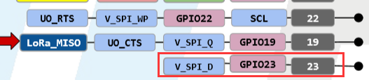
you can use GPIO23.
Thanks a lot for your advice!
But do you have any idea what is wrong with pin 12 ?
I’d like to know because I will have to use as many pins as possible for my project (flight controller for autonomous operation).
hi,
GPIO12 cannot be pulled high when connecting to a module, otherwise ESP32 will start abnormally. The SDA and SCL pins of BMP180 are both pulled up by default.
OK I’ve got it. GPIO12 is also MTDI, which changes the voltage of the internal LDO to 1.8V if pulled high at boot. Thanks a lot for your help, issue settled.
Hello guys
Thanks for your points on this topic. I have the Heltech OLED LoRa V2 board and I have been trying without success to interface BMP180, 280 DHT11 and read the sensor data. I ran the scan and the device I am working with now occupies 0x3C address.
Can anybody post a working sketch for this model that will solve this problem?
Thank you!
Hi,
0x3C is the I2C address of the OLED Display.
Hi Xiao-H
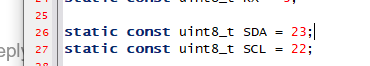
Thanks for the reply . I was able to get a BMP180 reading from address 0x76 on I2C one using SDA 21 and SCL 13.
Now to increase the font!
Appreciated.