Hi!
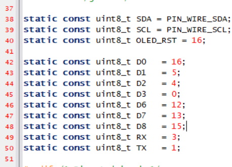
I have a 5 position mini-toggle switch (joystick) wired up to GPIO pins D3, D6, D7, D8. I have a 330 ohm resistor between each joystick/GPIO pin and GND. The common pole of the switch is connected to 3.3V. When the stick is engaged in one of the 4 directions, each pin is pulled from GND to 3.3V which I can then detect with digitalRead in my sketch.
Questions:
-
Are only 4 GPIO pins available to use on the WiFi 8? All other pins seem to have a conflict when testing them, and I really need the 5th pin to be able to detect the 5th direction on the joystick. Which pins are available for user GPIO?
-
In order to update the sketch on the ESP8266 using the Arduino IDE, I have to disconnect each of the 4 GPIO pins so that they are floating and not pulled to ground and then push the RST button. The RST button doesn’t work if any GPIO pins are pulled to ground. This makes resetting/programming a real problem. Should I be wiring the GPIO pins up differently?

