I’m using a Heltec Wifi Kit 32 V3 card
I use the GPIO4 and GPIO2 pins to read the two signals of an A-B incremental encoder (two square waves 90 degrees out of phase)
The idea is to use the falling edge of the GPIO2 pin (pin_B in the code) to check whether the GPIO4 pin (pin_A in the code) is high or low, and depending on the status of the GPIO4 pin increase or decrease the counter variable ’ which contains the number of steps counted up to the current moment
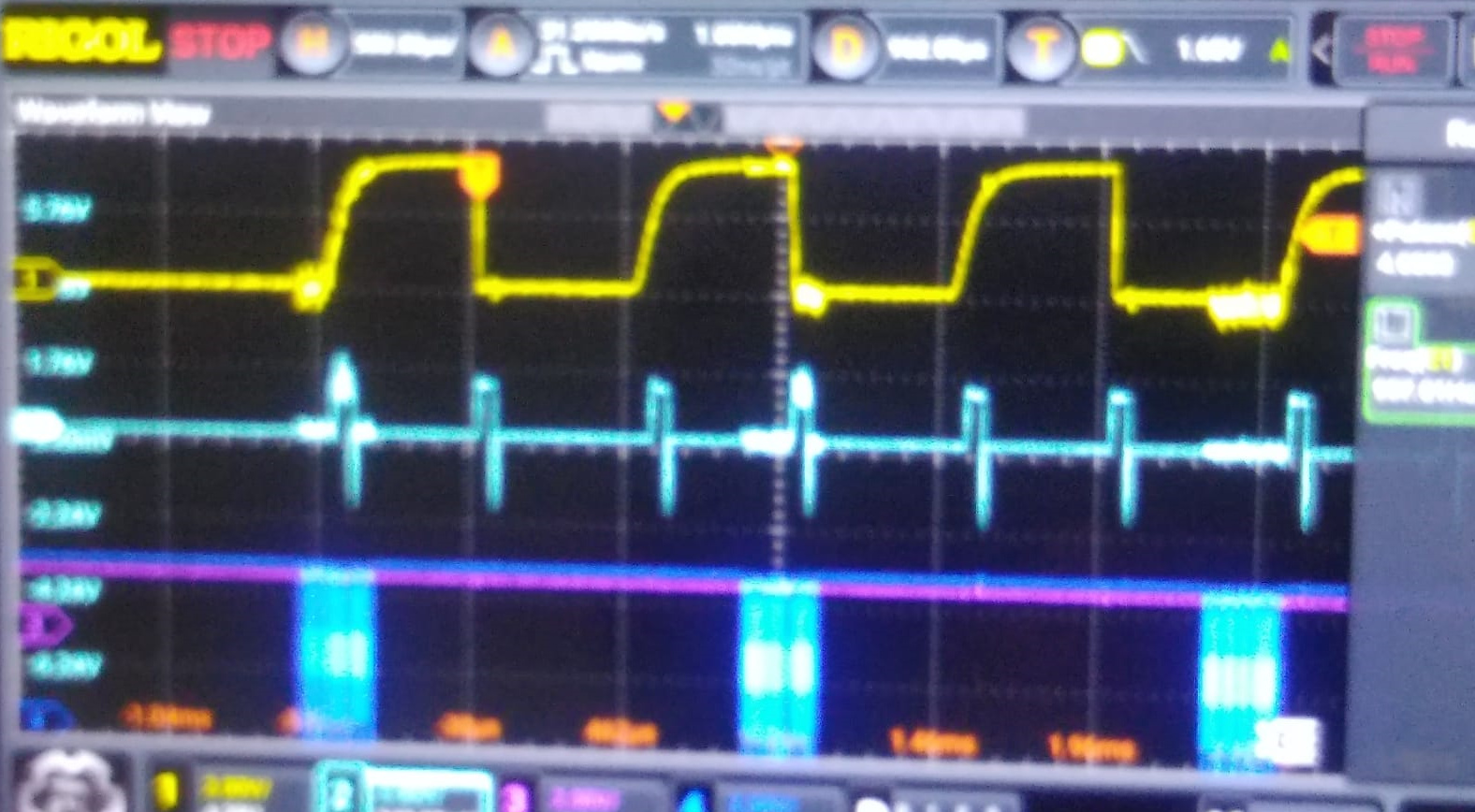
Inside the interrupt management routine I use a third pin, GPIO42 (pin_CLOCK_sync_interrupt in the code) as an output to verify with the oscilloscope exactly the moment of input and output in the routine
I am verifying that the interrupt management routine starts both on the falling edge and on the rising edge of the signal applied on the external GPIO2 pin
I can’t identify the problem in the code, so I would like to ask if:
1 Is the code set correctly?
2 Can the GPIO2 and GPIO4 pins be used as an interrupt source from an external signal?
3 For correct operation, what characteristics must the signal applied to pins GPIO2 and GPIO4 have (transition speed I mean)?
#include <Wire.h>
#define pin_A 4 // pin 15 - J2
#define pin_B 2 // pin 17 - J2
#define pin_CALIBRATE 6 // pin 13 - J2
#define pin_CLOCK_sync_interrupt 42
// Variabile per il conteggio
volatile unsigned int verso = 0;
volatile unsigned long conteggio ; // Esempio di valore iniziale per test
void IRAM_ATTR pin_A_isr_rising() {
digitalWrite(pin_CLOCK_sync_interrupt, HIGH);
// Leggi lo stato del pin A
bool stato_A = digitalRead(pin_A);
if (stato_A == HIGH) {
// Rotazione in senso orario
// Aggiungi qui il codice per la rotazione in senso orario
verso=1;
conteggio++;
} else {
// Rotazione in senso antiorario
// Aggiungi qui il codice per la rotazione in senso antiorario
verso=0;
conteggio–;
}
delay_rob(50);
digitalWrite(pin_CLOCK_sync_interrupt, LOW);
}
void delay_rob(unsigned long attesa_microsecondi) {
unsigned long tempoInizio = micros(); // Registra l’istante iniziale
while (micros() - tempoInizio < attesa_microsecondi) {
// Questo loop vuoto permette agli interrupt di essere eseguiti
// mentre si attende che passino ‘attesa_microsecondi’
}
}
void setup() {
Serial.begin(115200);
pinMode(pin_CLOCK_sync_interrupt, OUTPUT); digitalWrite(pin_CLOCK_sync_interrupt, LOW); // Assicurati che il pin sia basso all’avvio
pinMode(pin_A,INPUT);
pinMode(pin_B,INPUT);
pinMode(pin_CALIBRATE,INPUT);
attachInterrupt(digitalPinToInterrupt(pin_A), pin_A_isr_rising, FALLING);
conteggio=8000000;
Serial.println("----------------------");
Serial.println(String(conteggio));
}
void loop() {
verifica_pin_calibrate();
}
void verifica_pin_calibrate() {
int reading = digitalRead(pin_CALIBRATE);
if (digitalRead(pin_CALIBRATE) == LOW) {
Serial.println(“Pulsante CALIBRATE premuto…”);
delay_rob(20000);
}
}