WIFI KIT 32 V3 - Inaccurate interrupt code start times

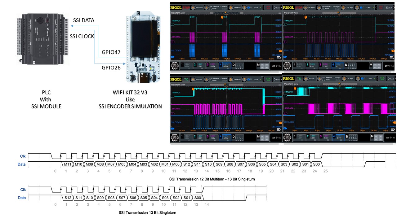
I’m trying to develop a routine for the transfer via serial line with SSI protocol of a 25 bit long word
In essence, the Wifi Kit 32 card simulates an encoder with an SSI interface
By connecting the “SSI card/Encoder” to the PLC, equipped with a specific standard SSI module, I expect to be able to correctly read from the PLC the value present inside the electronic card
The transmission from the electronic card to the PLC seems to work, but sometimes the data read seems totally incorrect
Looking at the electrical signals I see that the data line, driven by an output pin of the kit 32 wifi card, seems to be very imprecise compared to the clock signal edges
In essence, there seems to be an important tolerance between the moment of the falling edge of the clock signal, which must start the interrupt service routine, and the moment that the data line is activated
And this tolerance means that for every few hundred correct readings there is one wrong one
I attach the code I am using in the Arduino IDE environment
What could cause the lack of precision of the signal on the DATA line compared to the CLOCK signal?

#include <Arduino.h>
#include “esp_timer.h”
#include <Wire.h>
#include <WiFi.h>
#include <BluetoothSerial.h>

#define pin_CLOCK 26
#define pin_DATA 47

volatile unsigned int verso = 0;
volatile unsigned long conteggio=8000000;
volatile int numero_bit_inviati = 0;
volatile unsigned long conteggio_congelato_per_invio_a_plc = 0;

esp_timer_handle_t timer_durata_lettura_ssi;

void IRAM_ATTR pin_CLOCK_isr_falling() {
if (numero_bit_inviati == 0) {
digitalWrite(pin_CLOCK_sync_all_tx, HIGH);
esp_timer_stop(timer_durata_lettura_ssi);
esp_timer_start_once(timer_durata_lettura_ssi, 300);
numero_bit_inviati = 25;
conteggio_congelato_per_invio_a_plc = 6710886 ^ (6710886 >> 1);
} else {
numero_bit_inviati = numero_bit_inviati - 1;
}

digitalWrite(pin_DATA, (conteggio_congelato_per_invio_a_plc >> (numero_bit_inviati-2)) & 0x01);
}

void IRAM_ATTR onTimerDurataLetturaSsi(void* arg) {
numero_bit_inviati = 0;
digitalWrite(pin_DATA, HIGH);
digitalWrite(pin_CLOCK_sync_all_tx, LOW);
}

void setup() {
WiFi.disconnect(true);
WiFi.mode(WIFI_OFF);
btStop();

pinMode(pin_CLOCK, INPUT_PULLUP);
pinMode(pin_DATA, OUTPUT); digitalWrite(pin_DATA, HIGH);
attachInterrupt(digitalPinToInterrupt(pin_CLOCK), pin_CLOCK_isr_falling, FALLING);

const esp_timer_create_args_t timer_args_ssi = {.callback = &onTimerDurataLetturaSsi, .arg = NULL, .name = “timer_durata_lettura_ssi”};

esp_timer_create(&timer_args_ssi, &timer_durata_lettura_ssi);
}

void loop() {

}

Two dumb questions and an observation:

  1. Why load WiFi & BT and then disable it?
  2. How many people can read comments in Italian?

FreeRTOS is not implemented as a deterministic RTOS so timing in any calls in an ISR to stop one timer and start another will be inevitably glitch occasionally as you have discovered. Additionally, digitalWrite is a mega train wreck of lookups and validation and mode setting (it literally does pinMode() just to be sure).

Either cope with dropping the occasional packet or move the code to a single core MCU with hardware timers and direct writes to IO.

If you try to run radios as well I’d expect the dropped packet rate to rise. Compared to the C range, the original Xtensa based S range is pretty performant but you are not running real-time.

1- To make sure the peripherals are disabled
2- You’re right, I’ll delete them now

I also tried using portENTER_CRITICAL_ISR(&mux) as the first statement in the routine, and portEXIT_CRITICAL_ISR(&mux); for the last statement that serves the interrupt, but it doesn’t change anything

“…or move the code to a single core MCU with hardware timers and direct writes to IO…”
and how is this done? Is possible using Ide Arduino?

You’d have to check that the action of including the drivers doesn’t actually add to anything actually running.

You miss the point and it actually makes it worse by removing them - you may as well remove all the variable names in Italian as well. The point being that posting code on a predominately English language forum in another language restricts the number of people able to or inclined to answer - Google Translate isn’t perfect but it works.

Setting sections as critical doesn’t reduce the impact of turning timers on & off or calling the rather laborious digital write - it just reduces the chances of any other interrupts being actioned which as you’d have to define them isn’t likely to happen.

The original Arduino, the Uno, is a single core MCU with hardware timers & there are many places you can get code for direct access to the GPIO or use a library like FastIO - so sure, the Arduino IDE supports this. An Nano Every, an updated version with better hardware should have plenty of horsepower to do the job.

Anything you don’t initialize is not going to be active (BLE, WiFi) - this isn’t MicroPython. Interestingly, the ESP32-S3 does not even support the classic BluetoothSerial so I am not even sure how it compiles without complaining.

Also, interrupt code marked as IRAM_ATTR should be fast, faster, fastest and preferably even faster than the speed of light. Anything, anything that you can do to make it as fast as possible should be done, and will increase the chance of it working (such as optimizing things like digitalWrite, but also things like numero_bit_inviati-- instead of numero_bit_inviati = numero_bit_inviati - 1). But still, you will never be 100.0001% certain that you will get all your data relayed correctly.

I understand what you mean, and I apologize for it
I was hoping that given the very short size of the code it wouldn’t be a problem

I am convinced that with another CPU the work would be simpler, but this is not the question posed
I would like to understand exactly the reason for these times which are not well determinable and whether it is possible to remedy it in some way

Yes, thanks, I tried with the

numero_bit_inviati-- ; versus numero_bit_inviati=numero_bit_inviati-1 ;

and I found that the second is faster
I’m not sure why but measuring with the oscilloscope you can clearly see

I also tried replacing the classic digitalWrite with macros like this:

#define GPIO_SET_REG(GPIO_NUM) (GPIO.out_w1ts = (1 << GPIO_NUM))
#define GPIO_CLEAR_REG(GPIO_NUM) (GPIO.out_w1tc = (1 << GPIO_NUM))

or

#define GPIO_SET_REG(GPIO_NUM) (GPIO.out_w1ts = (1UL << GPIO_NUM))
#define GPIO_CLEAR_REG(GPIO_NUM) (GPIO.out_w1tc = (1UL << GPIO_NUM))

or

#define GPIO_SET_REG(GPIO_NUM) GPIO.out_w1ts.val = (1 << GPIO_NUM)
#define GPIO_CLEAR_REG(GPIO_NUM) GPIO.out_w1tc.val = (1 << GPIO_NUM)

but so far without success, in the sense that they do not seem to work correctly and the pin passed as a parameter to the macro does not physically change state

The short answer is that FreeRTOS on ESP32 is not configured to meet hard deadlines.

The longer answer may require you to learn rather a lot about how RTOS’s work.

Given the implementation for ESP32 it’s not possible to remedy it with the normal configuration - there may well be a way of turning off FreeRTOS but that means you’ll have to sort out your own timers.

So you’re saying it’s possible to disable rtos?
Do you know how to do it?
Is it possible to do it in Arduino Ide environment?

I gather it seems possible to disable most of the RTOS for one core.

In menuconfig when using IDF you can disable the tick on core 1. But I’ve not tried as, well, it’s trying to beat the whole setup in to a different shape than intended. If I need hard deadlines, I code to bare metal on something that will readily accept it, which the ESP32 isn’t really setup for.

By definition, no, not if you have to do it in IDF.

1 Like