
Can anyone tell me the UART RX TX pin on my Heltec. My Heltec pinout numbers are different from the picture on Amazon
UART pins on the Heltec wireless stick v3
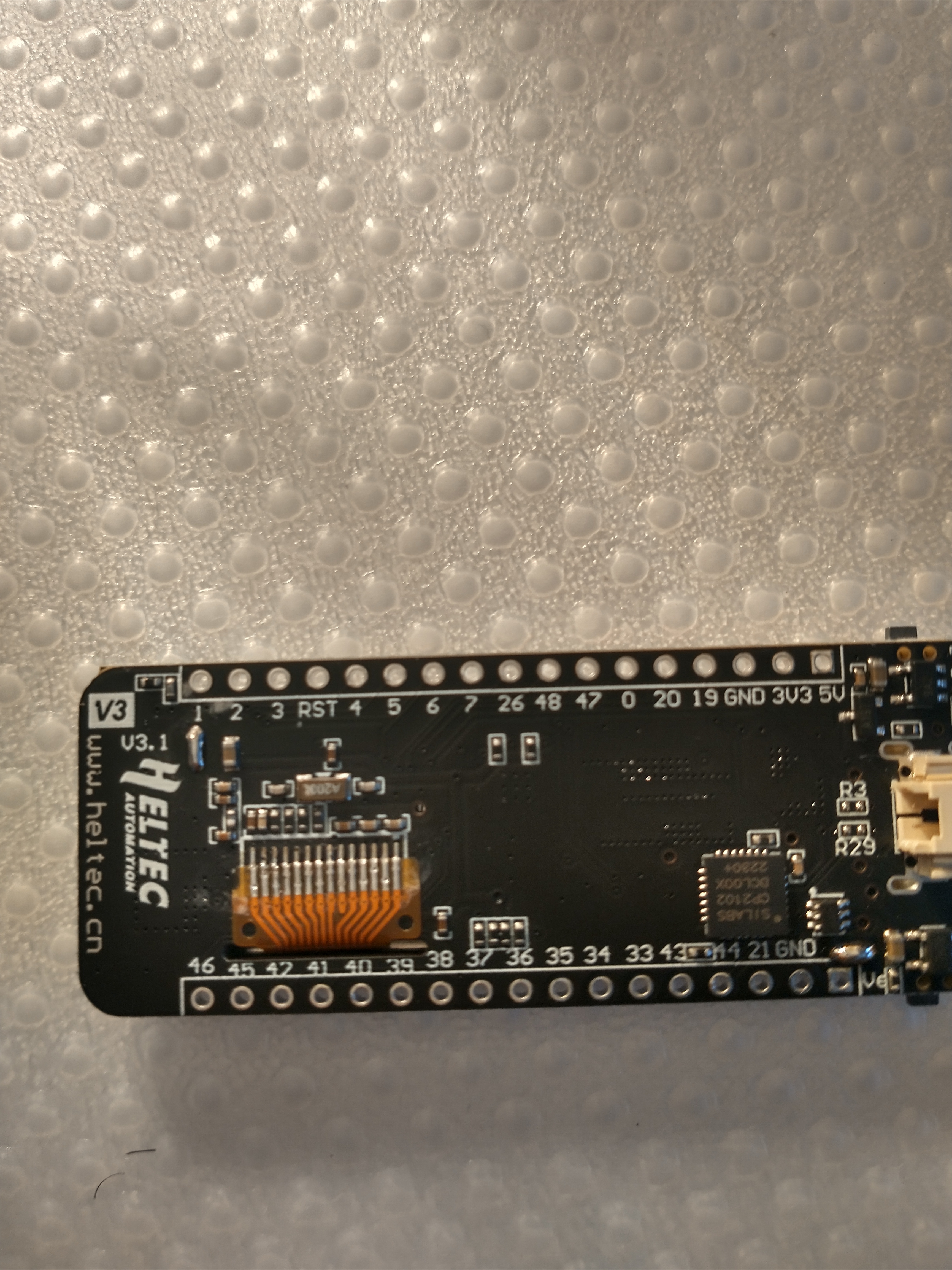
Check the Heltec Docs & Resource for the Wireless Stick module. The pin diagram there looks the same as your photo (except that it’s referencing the top of the board, while your photo is of the bottom of the board).
Do you know how much mah can the 3v3 pin supply?
Once again, if you check the Wireless Stick docs, I believe the number is 350mA.
EDIT: Correction. According to the Datasheet, the 3.3V pin should deliver 500mA.
1 Like
Why does my HTIT-WS_V3 board have the bottom of the board silk-screen completely different? My J3 Header has pin one at the bottom and this drawing shows J3-14 as RET where as my board has J3-RST as RST skipping pin numbers between 3 pin 3 and 4!
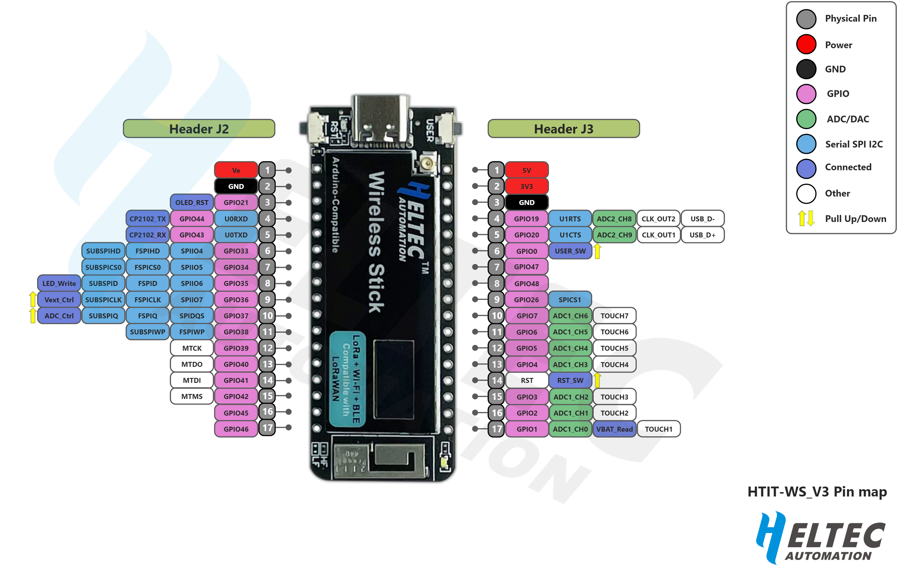
The HTIT-WSL_V3.png shows the top of the board with every pin given a sequel number (J3-1…20 J2-1…20) on the bottom of the board some pin functions match (REF, 5V, 3.3V etc) but the number are not the same, they appear to be random, pins J3-47, 48 while J2-40~46 and not in any order.
So what do we use to program with, the bottom Silk-Screen or the HTIT-WSL_V3.png ???
The silkscreen numbers are the relevant GPIO numbers (that you would use for programming). The numbers in the grey circles in the pin-out diagram are simply the numbering of the pins from one end of the relevant header—the GPIO numbers are those in the (generally) pink boxes next to the grey circles [in the pin-out diagram] and you will note that they ‘generally’ match the silkscreen.
Thanks, now it makes sense.
While ‘learning’ how to find things I discovered that the wireless stick V3 only has 17 pins a side while the wireless stick lite V3 has 20 pins a side and a defined Serial1 - How do I get a second serial port on the wireless stick V3?
ESP says there are 3 serial ports on the ESP32-S3.