Trying to share SPI-bus with LoRa and Epaper-display (Waveshare 2,9")

I am trying to share SPI with LoRa and I am using HeltecLoRa v2. LoRa part works fine but I dont get any response on display. My pin mapping is below:

//// Pin mapping
const lmic_pinmap lmic_pins = {
  .nss = 18,
  .rxtx = LMIC_UNUSED_PIN,
  .rst = 14,
  .dio = {26, 34, 35}, //oli 33,32
};


// BUSY -> 4, RST -> 16, DC -> 19, CS -> SS(5), CLK -> SCK(18), DIN -> MOSI(23), GND -> GND, 3.3V -> 3.3V
GxIO_Class io(SPI, /*CS=5*/ 15, /*DC=*/ 19, /*RST=*/ 16);
GxEPD_Class display(io, /*RST=*/ 16, /*BUSY=*/ 4);

What am I doing wrong?

BR,
Tuomo

I believe correct pin for MOSI is 27? I have tried using that + using CS,DC,RST and BUSY pins for free pins like 36,37,38,39 also. Still no success.

Hi:
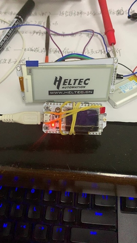
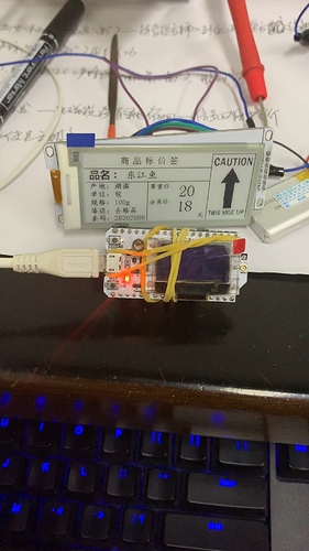
I tested it and it is possible to share the SPI with the LoRa part.
It is necessary to set different CSS pins for different peripherals.

Thanks for helping out! But I am still struggling with this issue.

What CS pin did you use for the other device (than LoRa).

Did you happen to test e-paper or some other SPI device?
Waveshare E-paper also requires DC, Busy and RST pins which I have tried to define on free pins 36-39

I did the same try as you. No abnormalities were found.
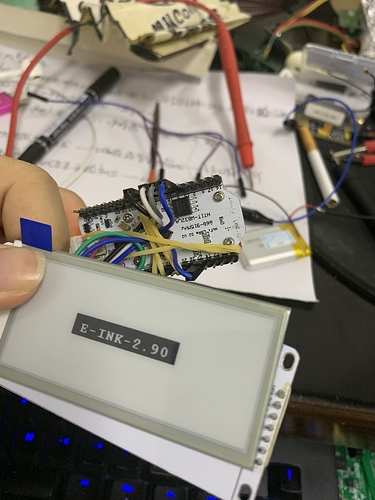
My e-ink 2.9 pin configuration is as follows:
BUSY–>23
CLK --> 5
CS -->18
SDI (MOSI)–>27
DC -->22

1 Like

Dear Saber, I am trying to connect the Waveshare 200x200 1.54inch Black&White E-Ink Display to the Heltec ESP32 LoRa V2 board.

For some reason, I cannot do it, though the board and the inbuilt OLED display work all right. Could you, please, post the code? Just some lines to display a “Hello world” string on the e-ink display.

[SOLVED] I connected exactly as Saber indicated, and it works all right. Both OLED and e-ink displays work fine.

1 Like

Dear Heltec team, dear Saber,

I have currently the same issue while connecting a Waveshare e-ink display (1.54") with a Wireless Stick lite. Currently neither the LoRa SX1276 chip nor the e-ink display are working if they are both configured in software. For LoRa I use a LMIC-clone library; for e-ink display I use GxEPD library.

I have the following config:
// SPI config (SX1276)
#define SPI_SCK 5 // GPIO5 – SX1276’s SCK
#define SPI_MISO 19 // GPIO19 – SX1276’s MISnO
#define SPI_MOSI 27 // GPIO27 – SX1276’s MOSI
#define SPI_SS 18 // GPIO18 – SX1276’s CS
#define SPI_RST 14 // GPIO14 – SX1276’s RESET
#define SPI_DI0 26 // GPIO26 – SX1276’s IRQ(Interrupt Request)
#define SPI_DI1 35 // GPIO35

And for the e-ink display I use:
/* SPI for ePaper
RED = 3.3V
BLACK = GND
BLUE = DIN = MOSI = D27
YELLOW = CLK = SCK = D5
ORANGE = CS = SS = D18
GREEN = DC = DC = D22
WHITE = RST = RESET = D3
PURPLE = BUSY = MISO = D23
*/
GxIO_Class io(SPI, 18, 22, 3); //SPI,SS,DC,RST
GxEPD_Class display(io, 3, 23); //io,RST,BUSY

Saber, in your posts you have written that two SPI devices can be connected together if they are using different CS lines. But you’ve connected the e-ink CS to the same CS line (18) of the hard wired SX1276. I don’t understand how it could work?

Thank you very much in advance.

I got it running now. LoRa SX1276 and the e-ink display are working together now.

I still have defined an different CS-line (21) for the e-ink. I shure that I did this already during my tests. But now it is really working. Maybe I had a loose contact problem with my experimental breadboard wiring.
So, the wiring and configuration for e-ink display now looks like:
/* SPI for ePaper
RED = 3.3V
BLACK = GND
BLUE = DIN = MOSI = D27
YELLOW = CLK = SCK = D5
ORANGE = CS = SS = D21
GREEN = DC = DC = D22
WHITE = RST = RESET = D3
PURPLE = BUSY = MISO = D23
*/
GxIO_Class io(SPI, 21, 22, 3); //SPI,SS,DC,RST
GxEPD_Class display(io, 3, 23); //io,RST,BUSY

I’m sorry for my last post.