T114 with Solar and Battery

Hi There,

I am having issues with my t114 with a battery and solar panel connected directly to the t114 in the right boards. The voltage doesn’t show the battery discharging properly and I am concerned it’s not charging the battery. I’d like the node to be completely off grid and have no maintenance.

I have read elsewhere that there may be a solution that uses a different board which will have the panel and battery connected. Can anyone give me advice on how to do this, point me in the right direction for a build or give any guidance.

Any help would be much appreciated.
Rolls

1 Like

What do you mean by the voltage display not showing normal discharge?
Currently, both ESP32 and nRF52840 have a random issue where some devices fail to boot during a slow voltage increase from low levels, requiring a reset operation. This makes maintenance-free operation somewhat challenging. We are communicating with the chip manufacturers to address this issue and hope to find a solution.

1 Like

Thanks for the speedy reply.

Sorry, I should have been clearer. I have a battery and solar panel plugged into my t114 JST ports. I’m not sure the battery is recharging from the solar panel properly and the t114 is correctly registering the battery voltage.

Hopefully that makes more sense.
Rolls

I’ve wired my Heltec T114 to a small solar panel and battery, but the reported battery voltage never changes—it just sits at the same value day and night—so the board never seems to charge or discharge the battery, and I can’t get a truly self-sustaining, off-grid node running.

How are you currently measuring? Without knowing how you are doing this, it’s so very hard to comment in detail.

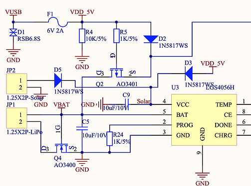
I’ll leave @richard3366 to comment on the schematic which appears to show the charge LED connected to CE and no connection to power, unlike in v1 which has it.

Assuming the charge LED is operational and ignoring the translation of the data sheet , does yours come on when the solar panel is in sunshine?

Can you measure the voltage on the solar panel and the battery using a multimeter with both the solar panel plugged in and without?

Are you using some code to measure the BAT_ADC input? Are you accounting for the charger pushing this value to what will appear to be a full battery whilst it is being charged? Without being able to disable the charger chip, during the day the battery level is hard to measure. In the dark the charger chip won’t be charging so you get the real battery voltage.

This is a common issue with solar systems. The simple solution is to alter the board to allow you to pull the charger chip CE input low programatically.

1 Like

Thanks for the response. I’m basing the battery level purely off the voltage readout. Yes, the orange light comes on when is charging. Funnily it doesn’t immediately drop at night but does change overnight. It doesn’t seem to drop as you might expect i e gradually overnight. It will decrease 0.03 to 0.05V but no more.

I haven’t calibrated the voltage on ADC which can be done on Meshtastic but that shouldn’t make a difference.

I’m plugged directly into the jst ports of my t114. There is a solar and battery connection directly on the board.

Which voltage readout? Using what tester / device / code and where are the probes put if it’s a tester?

When you say the voltage drops overnight, what is the unit doing - asleep or turned off? Is it plugged in to USB?

It’s good to see some numbers, but we are still very much in the dark about what actual hard values are. What is the voltage on the battery when:

  • USB is plugged in
  • No USB but solar plugged in in bright light / sunshine
  • No USB or solar plugged in immediately after disconnecting them
  • No USB or solar after 6 hours of the unit being turned on, even if idle

And please try to be more expansive with your details - it will enable people to help you reach a solution faster. Remember, what’s obvious to you on the bench in front of you we can’t see. So any descriptions need to be clear and measured values are everything.

1 Like

Hi There, thanks for taking the time to respond and the pointers on what I should include.

Here is a details description of my system:
Components
T114 board
6000mAh 18650 battery
10W 6V output solar panel

Connections
6000mAh battery ----->[JST connector “Bat”] T114 Board [JST connector “solar”] <----------6V 10W Solar Panel

I am measuring the displayed voltage on the T114 board readout. I don’t have a tester. The USB port is NOT plugged in.

The unit is always on. I have enabled the low power mode on the Meshtastic software i.e. BLE and WiFI disabled and set up as a client device. The unit will transmit it’s battery level, which is how I am monitoring it.

The voltage drops when it gets dark, overnight. Falling by 0.02-0.03V. However the voltage doesn’t drop below 4.06V (89%) and seems to get stuck there when I might expect it to drop lower. i.e. it will sit there for a couple of days.

When I assembled it I tested and the orange charging light came on for both a USB connection (since removed) and when the solar panel was illuminated.

During initial assembly, voltage with USB mains power: 100% 4.26V. Which agrees with other V3 boards I have.

Sorry the unit is in-situ and I can’t easily plug in a USB source. I have the battery connected to the JST port on the T114 board.

I’ve had it installed outside for about 2 weeks.

I hope this is more expansive and sorry I can’t change connections for troubleshooting.

Rolls

A simple good-enough multimeter can be had off Amazon and will inform you of what is actually happening so much more - for the low low investment of ~$5.

The maximum capacity on the market for this battery size is ~2,500mAh/

Best will in the world, Meshtastic can cope with a few minutes of downtime. If there is something screwy going on with charging, as there is definitely something odd going on, best to find out early on before you really do absolutely rely on it.

Without a meter, the only other test is to unplug the solar for a day or so and see if the voltage does ever get below 4.06V. The natural resting point for LiPo is 3.8V, so I’d expect it to drop to that and then hang around at that level for a while. Which it might be doing if the Vbat reading is over by 2V

1 Like

Sorry, should have said this is a 3 bank of 18650 batteries.

Thank you for the helpful suggestions. I can easily pull the plug on the solar and see how it goes. I’ve got a multimeter to hand and I should be able to access it at some point soon.

I’m a little concerned that the solar is drawing on the battery when it is dark. I’m not confident I understand how the T114 board should be controlling the battery and panel when they are both plugged in. My electronics are rudimentary at best.

Thanks again. I’ll post back what I find, when I find it.

Rolls

With a triple 18650 bank, you won’t see much voltage drop on a maximum power saving setup. Best to unplug / cover the solar panel for a couple of days.

It can’t.

Just learn one little bit at a time, it soon builds up, have a look at the schematic and you’ll see that there are three 1N5817W Schottky diodes on the power inputs to prevent back flow for the solar panel, the USB or the 5V input pin.

There are also two MOSFETs (super efficient transistors).

Q2 to turn off the battery connection when there is power from USB or 5V pin. It only conducts when its gate (base) has no power, ie when there’s no external power.

The other, Q4, provides reverse polarity connection on the battery. It only conducts when it has a positive voltage on it, so when the battery is the right way round, it turns on Q4 which completes the battery connection.

But as @BNS says, with three batteries you aren’t going to see much voltage drop on a deep sleep device.

Great that you’ve automagiced a multimeter, would be worth checking what reality is when it is reporting 4.06V because you so don’t want to have it reporting 3.2V when it’s actually a mildly compromised 3.0V. Three batteries in parallel won’t take a liking to that.

1 Like

Just for the record, I’m using CubeCells not T114s, but the power consumption is similar. My nodes run on a single 900mAh 14500 Li-Ion battery and 5V or 5.5V solar panels as small as 200mW, transmitting [their battery voltage level, amongst other things, via LoRa] every 60 seconds. My location does enjoy generally good weather but the battery voltage never falls below 4.0V. Overnight it drops 0.1V at most (from 4.10~4.12V) but it starts recharging as soon as it becomes daylight and before the sun even rises. It’s now 7.30 am on a lightly overcast day, the sun is barely over the horizon and the batteries on my nodes are all showing between 4.02 and 4.12V (the ones that were not already fully recharged have recharged 0.02V just while I’ve been typing this response). The batteries recharge, if not fully, even on heavily overcast days. This has been the pattern for over two years now. These things don’t need much juice…

1 Like

Thanks for the info @UniquePete and @nmcc. That’s really helpful. Much more than I got from googling and LLM. I live at quite high latitude hence the chunky battery. I’ll check over the next week and see how it goes.

Ok, I covered the panel for 48 hours and set it into the router mode in Meshtastic. It had a higher battery usage. I got a drop of 4% in 2 days. Which is more than any time before. I’m feeling much more confident the battery and panel are cycling charge and discharge. I’ve a couple more weeks of my initial trial before deployment. Thanks again for your help. I’ll post here how it went.