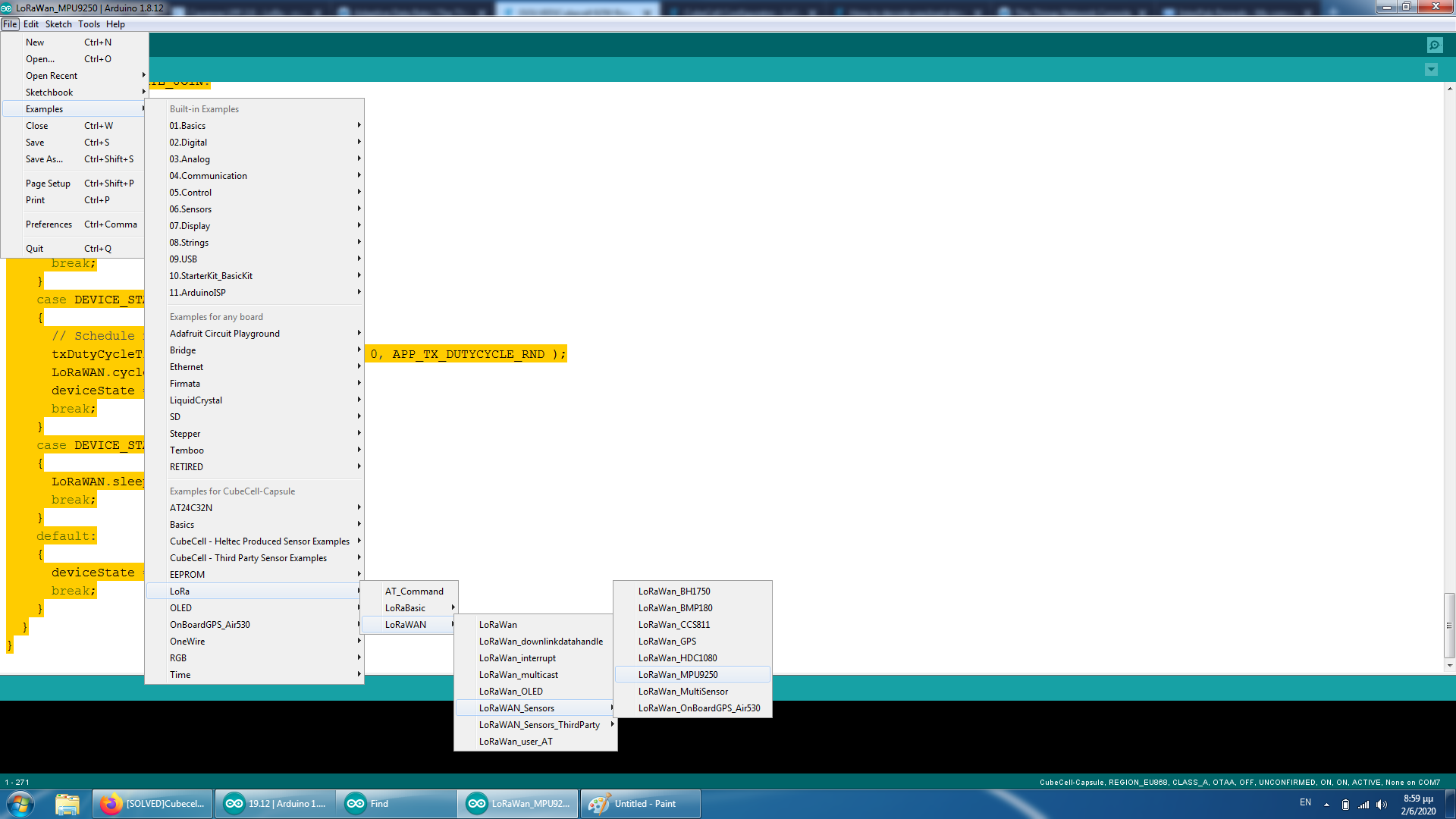
Well my coding skills arent top notch, by the way i used the dedicated code for this device combo under the arduino ide and it seems to work in payload perspective but gives me values of latitude, Longtitude and temperature which is not what MPU9250 gives.
#include “LoRaWan_APP.h”
#include “Arduino.h”
#include <Wire.h>
#include <MPU9250.h>
/*
- set LoraWan_RGB to Active,the RGB active in loraWan
- RGB red means sending;
- RGB purple means joined done;
- RGB blue means RxWindow1;
- RGB yellow means RxWindow2;
- RGB green means received done;
*/
/* OTAA para*/
uint8_t devEui[] = { 0x22, 0x32, 0x33, 0x00, 0x00, 0x88, 0x88, 0x02 };
uint8_t appEui[] = { 0x00, 0x00, 0x00, 0x00, 0x00, 0x00, 0x00, 0x00 };
uint8_t appKey[] = { 0x88, 0x88, 0x88, 0x88, 0x88, 0x88, 0x88, 0x88, 0x88, 0x88, 0x88, 0x88, 0x88, 0x88, 0x66, 0x01 };
/* ABP para*/
uint8_t nwkSKey[] = { 0x15, 0xb1, 0xd0, 0xef, 0xa4, 0x63, 0xdf, 0xbe, 0x3d, 0x11, 0x18, 0x1e, 0x1e, 0xc7, 0xda,0x85 };
uint8_t appSKey[] = { 0xd7, 0x2c, 0x78, 0x75, 0x8c, 0xdc, 0xca, 0xbf, 0x55, 0xee, 0x4a, 0x77, 0x8d, 0x16, 0xef,0x67 };
uint32_t devAddr = ( uint32_t )0x007e6ae1;
/LoraWan channelsmask, default channels 0-7/
uint16_t userChannelsMask[6]={ 0x00FF,0x0000,0x0000,0x0000,0x0000,0x0000 };
/LoraWan region, select in arduino IDE tools/
LoRaMacRegion_t loraWanRegion = ACTIVE_REGION;
/LoraWan Class, Class A and Class C are supported/
DeviceClass_t loraWanClass = LORAWAN_CLASS;
/the application data transmission duty cycle. value in [ms]./
uint32_t appTxDutyCycle = 15000;
/OTAA or ABP/
bool overTheAirActivation = LORAWAN_NETMODE;
/ADR enable/
bool loraWanAdr = LORAWAN_ADR;
/* set LORAWAN_Net_Reserve ON, the node could save the network info to flash, when node reset not need to join again */
bool keepNet = LORAWAN_NET_RESERVE;
/* Indicates if the node is sending confirmed or unconfirmed messages */
bool isTxConfirmed = LORAWAN_UPLINKMODE;
/* Application port /
uint8_t appPort = 2;
/!
- Number of trials to transmit the frame, if the LoRaMAC layer did not
- receive an acknowledgment. The MAC performs a datarate adaptation,
- according to the LoRaWAN Specification V1.0.2, chapter 18.4, according
- to the following table:
- Transmission nb | Data Rate
- ----------------|-----------
- 1 (first) | DR
- 2 | DR
- 3 | max(DR-1,0)
- 4 | max(DR-1,0)
- 5 | max(DR-2,0)
- 6 | max(DR-2,0)
- 7 | max(DR-3,0)
- 8 | max(DR-3,0)
- Note, that if NbTrials is set to 1 or 2, the MAC will not decrease
- the datarate, in case the LoRaMAC layer did not receive an acknowledgment
*/
uint8_t confirmedNbTrials = 4;
/* Prepares the payload of the frame */
MPU9250 mySensor;
static void prepareTxFrame( uint8_t port )
{
/*appData size is LORAWAN_APP_DATA_MAX_SIZE which is defined in “commissioning.h”.
*appDataSize max value is LORAWAN_APP_DATA_MAX_SIZE.
*if enabled AT, don’t modify LORAWAN_APP_DATA_MAX_SIZE, it may cause system hanging or failure.
*if disabled AT, LORAWAN_APP_DATA_MAX_SIZE can be modified, the max value is reference to lorawan region and SF.
*for example, if use REGION_CN470,
*the max value for different DR can be found in MaxPayloadOfDatarateCN470 refer to DataratesCN470 and BandwidthsCN470 in “RegionCN470.h”.
*/
float aX, aY, aZ, aSqrt, gX, gY, gZ, mDirection, mX, mY, mZ;
pinMode(Vext, OUTPUT);
digitalWrite(Vext, LOW);
Wire.begin();
mySensor.setWire(&Wire);
mySensor.beginAccel();
mySensor.beginGyro();
mySensor.beginMag();
// You can set your own offset for mag values
// mySensor.magXOffset = -50;
// mySensor.magYOffset = -55;
// mySensor.magZOffset = -10;
mySensor.accelUpdate();
aX = mySensor.accelX();
aY = mySensor.accelY();
aZ = mySensor.accelZ();
aSqrt = mySensor.accelSqrt();
Serial.print(“aX:”);
Serial.println(aX);
Serial.print(“aY:”);
Serial.println(aY);
Serial.print(“aZ:”);
Serial.println(aZ);
Serial.print(“aSqrt:”);
Serial.println(aSqrt);
mySensor.gyroUpdate();
gX = mySensor.gyroX();
gY = mySensor.gyroY();
gZ = mySensor.gyroZ();
Serial.print(“gX:”);
Serial.println(gX);
Serial.print(“gY:”);
Serial.println(gY);
Serial.print(“gZ:”);
Serial.println(gZ);
mySensor.magUpdate();
mX = mySensor.magX();
mY = mySensor.magY();
mZ = mySensor.magZ();
mDirection = mySensor.magHorizDirection();
Serial.print(“mX:”);
Serial.println(mX);
Serial.print(“mY:”);
Serial.println(mY);
Serial.print(“mZ:”);
Serial.println(mZ);
Serial.print(“mDirection:”);
Serial.println(mDirection);
Wire.end();
digitalWrite(Vext, HIGH);
uint16_t batteryVoltage = getBatteryVoltage();
unsigned char *puc;
puc = (unsigned char *)(&aX);
appDataSize = 46;
appData[0] = puc[0];
appData[1] = puc[1];
appData[2] = puc[2];
appData[3] = puc[3];
puc = (unsigned char *)(&aY);
appData[4] = puc[0];
appData[5] = puc[1];
appData[6] = puc[2];
appData[7] = puc[3];
puc = (unsigned char *)(&aZ);
appData[8] = puc[0];
appData[9] = puc[1];
appData[10] = puc[2];
appData[11] = puc[3];
puc = (unsigned char *)(&gX);
appData[12] = puc[0];
appData[13] = puc[1];
appData[14] = puc[2];
appData[15] = puc[3];
puc = (unsigned char *)(&gY);
appData[16] = puc[0];
appData[17] = puc[1];
appData[18] = puc[2];
appData[19] = puc[3];
puc = (unsigned char *)(&gZ);
appData[20] = puc[0];
appData[21] = puc[1];
appData[22] = puc[2];
appData[23] = puc[3];
puc = (unsigned char *)(&mX);
appData[24] = puc[0];
appData[25] = puc[1];
appData[26] = puc[2];
appData[27] = puc[3];
puc = (unsigned char *)(&mY);
appData[28] = puc[0];
appData[29] = puc[1];
appData[30] = puc[2];
appData[31] = puc[3];
puc = (unsigned char *)(&mZ);
appData[32] = puc[0];
appData[33] = puc[1];
appData[34] = puc[2];
appData[35] = puc[3];
puc = (unsigned char *)(&aSqrt);
appData[36] = puc[0];
appData[37] = puc[1];
appData[38] = puc[2];
appData[39] = puc[3];
puc = (unsigned char *)(&mDirection);
appData[40] = puc[0];
appData[41] = puc[1];
appData[42] = puc[2];
appData[43] = puc[3];
appData[44] = (uint8_t)(batteryVoltage>>8);
appData[45] = (uint8_t)batteryVoltage;
Serial.print(“BatteryVoltage:”);
Serial.println(batteryVoltage);
}
void setup() {
boardInitMcu();
Serial.begin(115200);
#if(AT_SUPPORT)
enableAt();
#endif
deviceState = DEVICE_STATE_INIT;
LoRaWAN.ifskipjoin();
}
void loop()
{
switch( deviceState )
{
case DEVICE_STATE_INIT:
{
#if(AT_SUPPORT)
getDevParam();
#endif
printDevParam();
LoRaWAN.init(loraWanClass,loraWanRegion);
deviceState = DEVICE_STATE_JOIN;
break;
}
case DEVICE_STATE_JOIN:
{
LoRaWAN.join();
break;
}
case DEVICE_STATE_SEND:
{
prepareTxFrame( appPort );
LoRaWAN.send();
deviceState = DEVICE_STATE_CYCLE;
break;
}
case DEVICE_STATE_CYCLE:
{
// Schedule next packet transmission
txDutyCycleTime = appTxDutyCycle + randr( 0, APP_TX_DUTYCYCLE_RND );
LoRaWAN.cycle(txDutyCycleTime);
deviceState = DEVICE_STATE_SLEEP;
break;
}
case DEVICE_STATE_SLEEP:
{
LoRaWAN.sleep();
break;
}
default:
{
deviceState = DEVICE_STATE_INIT;
break;
}
}
}