
Hello, I am using the Heltec CubeCell HTCC-AB02 board (https://heltec.org/project/htcc-ab02/), and the charging system with the solar panel does not work.
I have an AK68x37 solar panel connected, its voltage is 5v and the peak current is 60mA. The exact characteristics are in this link: https://tienda.bricogeek.com/placas-solares/1367-panel-solar-300mw-5v-ak68x37.html the panel is connected to Vs and gnd, the battery I am using is 1000mA and is connected to the port that the Heltec board has by default, but it does not charge at all. Could you help me by telling me what I’m doing wrong or why the charging system isn’t working? Do I have to change the panel or what can be done?
Solar panel without charging the battery on Heltec htcc-ab02 board
I use a similar arrangement (AB02 + 50mA/60mA/70mA 5V/5.5V solar panel + 14500 Li-Ion battery) in several projects. In my environment (a sunny part of Australia), a 50mA panel keeps the battery fully charged with the processor on something like an 8% duty cycle (5 sec on, then 55 sec in deep sleep).
How have you determined that the battery is not charging? The battery may well be showing a net discharge if you’re using more power than the panel is generating.
Thank you for your response. I am in the equatorial zone, Colombia, here the climate varies a lot.
I am currently measuring the battery percentage with the lines of code (batteryVoltage)
When I connect the panel and there is sunlight without any intensity, the battery has the same value as with the panel,
On the other hand, when the sun is at great intensity, the value of the battery goes up, but when the solar panel is covered, it discharges again to the value of the battery. Let me explain.
when I have the
battery with panel without sunlight at high intensity the value it gives me is 3500, when the sunlight increases the battery rises to 3700
but as soon as I cover the sunlight it returns to its normal value 3500, so I have concluded that the panel only helps in power when there is a sufficient amount of sun but it does not charge the battery because the moment the sun goes away the battery returns to normal. its normal value.
The system that is connected to the Heltec board has a discharge of 0.2A in case it is useful to help me see what problem I may be having and all all the sensors of these are connected to VDD
It’s difficult to comment without seeing the actual code that you are using. In my experience, however, there is no difference in the instantaneous measurement of battery voltage when a solar panel that is connected to a charging circuit is in sunlight vs darkness. I did use a SunAir INA3221 breakout board at one point to measure instantaneous currents within the charging system, and that was perhaps more informative in the present context.
When I was initially testing solar panels, however, to see what size would be sufficient, I started out by simply running a processor, reading a BME280 sensor and reporting the battery voltage (in a packet transmitted via LoRa, although the same could be achieved by simply displaying the battery voltage on an OLED display) without a solar panel and watching how the battery voltage level depleted over several days (a purely empirical approach).
I then attached various solar panels to the processor/charging system and again observed the battery voltage over several days. In my configuration, with any panel of more than about 50mA/5V, the [Li-Ion] battery would charge to about 4.2V during the daytime, then run down to about 4.0-4.1V overnight. It usually took a couple of hours at most to recharge the battery once the sun came out, but the battery would recharge, albeit more slowly, even in overcast conditions.
Either way, observing the behaviour over a longer time period (hours or days) might be more informative.
The code I am using is the one that Lorawan comes with by default but I adapted an SCD30 sensor to it. the code is the following:
#include “LoRaWan_APP.h”
#include “Arduino.h”
#include <Wire.h>
#include “SCD30.h”
#include “innerWdt.h”
/*
- set LoraWan_RGB to Active,the RGB active in loraWan
- RGB red means sending;
- RGB purple means joined done;
- RGB blue means RxWindow1;
- RGB yellow means RxWindow2;
- RGB green means received done;
*/
/* OTAA para*/
uint8_t devEui[] = { 0x70, 0xB3, 0xD5, 0x7E, 0xD0, 0x06, 0x00, 0x8E };
uint8_t appEui[] = { 0x00, 0x00, 0x00, 0x00, 0x00, 0x00, 0x00, 0x00 };
uint8_t appKey[] = { 0x88, 0x88, 0x88, 0x88, 0x88, 0x88, 0x88, 0x88, 0x88, 0x88, 0x88, 0x88, 0x88, 0x88, 0x66, 0x01 };
/* ABP para*/
uint8_t nwkSKey[] = { xxxxxxxxxxxxxxxxxxxxxxxxxxxxxxxxxx };
uint8_t appSKey[] = { xxxxxxxxxxxxxxxxxxxxxxxxxxxxxxxxxx };
uint32_t devAddr = ( uint32_t )0xxxxxxxx;
/LoraWan channelsmask, default channels 0-7/
uint16_t userChannelsMask[6]={ 0xFF00,0x0000,0x0000,0x0000,0x0000,0x0000 };
/LoraWan region, select in arduino IDE tools/
LoRaMacRegion_t loraWanRegion = ACTIVE_REGION;
/LoraWan Class, Class A and Class C are supported/
DeviceClass_t loraWanClass = LORAWAN_CLASS;
/the application data transmission duty cycle. value in [ms]./
uint32_t appTxDutyCycle = 10000;
/OTAA or ABP/
bool overTheAirActivation = LORAWAN_NETMODE;
/ADR enable/
bool loraWanAdr = LORAWAN_ADR;
/* set LORAWAN_Net_Reserve ON, the node could save the network info to flash, when node reset not need to join again */
bool keepNet = LORAWAN_NET_RESERVE;
/* Indicates if the node is sending confirmed or unconfirmed messages */
bool isTxConfirmed = LORAWAN_UPLINKMODE;
/* Application port /
uint8_t appPort = 2;
/!
- Number of trials to transmit the frame, if the LoRaMAC layer did not
- receive an acknowledgment. The MAC performs a datarate adaptation,
- according to the LoRaWAN Specification V1.0.2, chapter 18.4, according
- to the following table:
- Transmission nb | Data Rate
- ----------------|-----------
- 1 (first) | DR
- 2 | DR
- 3 | max(DR-1,0)
- 4 | max(DR-1,0)
- 5 | max(DR-2,0)
- 6 | max(DR-2,0)
- 7 | max(DR-3,0)
- 8 | max(DR-3,0)
- Note, that if NbTrials is set to 1 or 2, the MAC will not decrease
- the datarate, in case the LoRaMAC layer did not receive an acknowledgment
*/
uint8_t confirmedNbTrials = 4;
/* Prepares the payload of the frame */
static void prepareTxFrame( uint8_t port )
{
/*appData size is LORAWAN_APP_DATA_MAX_SIZE which is defined in “commissioning.h”.
*appDataSize max value is LORAWAN_APP_DATA_MAX_SIZE.
*if enabled AT, don’t modify LORAWAN_APP_DATA_MAX_SIZE, it may cause system hanging or failure.
*if disabled AT, LORAWAN_APP_DATA_MAX_SIZE can be modified, the max value is reference to lorawan region and SF.
*for example, if use REGION_CN470,
*the max value for different DR can be found in MaxPayloadOfDatarateCN470 refer to DataratesCN470 and BandwidthsCN470 in “RegionCN470.h”.
if (scd30.isAvailable()) {
scd30.getCarbonDioxideConcentration(result);
    //Almacenar los valores en variables
    float co2Concentracion = result[0];
    float temperatura = result[1];
    float humedad = result[2];

    long  co2 =co2Concentracion*1000;
    long  temp = temperatura*1000;
    long  hum = humedad*1000;

    appDataSize = 12;
    appData[0]= co2 >> 24;
    appData[1]= co2 >> 16;
    appData[2]= co2 >> 8;
    appData[3]= co2;

    appData[4]= temp >> 24;
    appData[5]= temp >> 16;
    appData[6]= temp >> 8;
    appData[7]= temp;

    appData[8]= hum >> 24;
    appData[9]= hum >> 16;
    appData[10]= hum >> 8;
    appData[11]= hum;

    uint16_t batteryVoltage = getBatteryVoltage();

    appData[12] = (uint8_t)(batteryVoltage>>8);
    appData[13] = (uint8_t)batteryVoltage;

    Serial.print("Carbon Dioxide Concentration is: ");
    Serial.print(co2Concentracion);
    Serial.println(" ppm");
    Serial.print("Temperature = ");
    Serial.print(temperatura);
    Serial.println(" ℃");
    Serial.print("Humidity = ");
    Serial.print(humedad);
    Serial.println(" %");

    Serial.print(F(", Bateria="));
    Serial.println(batteryVoltage);


}
}
void setup() {
Serial.begin(115200);
Wire.begin();
scd30.initialize();
#if(AT_SUPPORT)
enableAt();
#endif
deviceState = DEVICE_STATE_INIT;
LoRaWAN.ifskipjoin();
}
void loop()
{
switch( deviceState )
{
case DEVICE_STATE_INIT:
{
#if(LORAWAN_DEVEUI_AUTO)
LoRaWAN.generateDeveuiByChipID();
#endif
#if(AT_SUPPORT)
getDevParam();
#endif
printDevParam();
LoRaWAN.init(loraWanClass,loraWanRegion);
deviceState = DEVICE_STATE_JOIN;
break;
}
case DEVICE_STATE_JOIN:
{
LoRaWAN.join();
break;
}
case DEVICE_STATE_SEND:
{
prepareTxFrame( appPort );
LoRaWAN.send();
deviceState = DEVICE_STATE_CYCLE;
break;
}
case DEVICE_STATE_CYCLE:
{
// Schedule next packet transmission
txDutyCycleTime = appTxDutyCycle + randr( 0, APP_TX_DUTYCYCLE_RND );
LoRaWAN.cycle(txDutyCycleTime);
deviceState = DEVICE_STATE_SLEEP;
break;
}
case DEVICE_STATE_SLEEP:
{
LoRaWAN.sleep();
break;
}
default:
{
deviceState = DEVICE_STATE_INIT;
break;
}
}
}
I have already done tests for several days with the 1000mA battery and the longest it lasts is 23 hours with the solar panel connected or not, so for this reason I assume that the charging system is not working for me
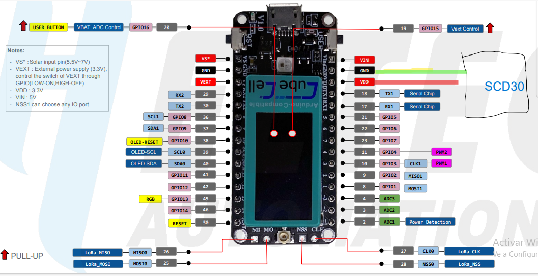
los sensores los tengo conectados asi:
Are you able to check the [voltage/current] output of the solar panel? And just to be sure, you are connecting the positive pad on the solar panel to the Vs pin and the negative pad to one of the GND pins? And all of your solder joints are ‘good’?
The only other thing I could suggest, to check the operation of the charging system at least, is disconnecting the sensor and just running, for example, the factory test program (with nothing other than the battery connected, through the JST connector on the bottom of the board). If you’re going to be running from battery, even with a solar panel, you’re probably not going to be able to run the processor continuously, so you’ll most likely be wanting to connect the sensor to Vext in any case, and only switch it ON to make periodic measurements.
Thank you very much for responding, I have been doing tests these days and I have these news.
If I have the positive connected to vs and the negative to gnd, the cables and solders are in good condition if there is continuity.
I already tried leaving only the solar panel with the battery but it didn’t work, the battery was still not charging, I checked that the battery was good by charging with a battery charger and it is indeed good.
doing voltage tests and reading several of the forums about this problem, I observed that the minimum voltage of the panel is 4.2v, I checked this and indeed the panel gives more than 4.2 volts, it gives 4.3v to 4.5 without sun, but when measuring the voltage in vs and gnd the voltjae there is 3.78v do you think that would be the problem? and how could it be solved?
When you tell me to turn it on only for periodic measurements, are you referring to the sensor?
Unfortunately I’m travelling for the next week and can’t do any measuring of my own. As I recall, though, the Heltec specs suggest that the panel voltage needs to be in the range 5.5-7V (although I have used 5V panels without any problem). I don’t know enough about the way the TP4056 IC works to comment on the impact of supplying a lower voltage, but I don’t know that I would be very optimistic about charging what is effectively a 4.2V battery with a 3.8V power source…
I have just measured the voltage generated by several different sized solar panels that I use. The panels are rated at 5V, 5.5V and 6V. It is overcast here today and the lowest voltage I have measured on any panel is 5.2V (this for a 5V/30mA panel). The 5.5V panels (40mA - 180mA) are typically showing around 5.7V and the 6V (330mA) panel is showing 6V. When it comes to charging a battery though, it will be the current generated by the panel that will determine whether or not it will charge the battery.
So, for example, with a 5V/60mA panel, I read 5.4V when disconnected and 4.6V when connected to the AB02 (with 900mAh 14500 Li-Ion battery and not powering anything else, but there is a ‘protection’ diode also in the circuit), but with a 5.5V/40mA panel, while it reads 5.7V when disconnected, it reads only 0.7V when connected to the AB02 (i.e. it cannot generate the current required to charge the battery).
With regard to the comment about Vext, yes, I was referring to the sensor, but when running from battery you will also want to be sleeping the processor when it’s not reading the sensor or transmitting data.
Thank you very much for your response,
looking at the values they gave you, these values are greater than 4.2, which is the minimum required for the panel to charge. I think I will try to buy a panel with a higher current and see if that solves my problem.
Regarding Vext, when connecting the battery I obtain zero values by measuring Vext and GND, connect an LED to the output to observe its behavior and it lights up as does the LED on the board that sends the lorawam data, the programming is every 15 seconds, therefore every 15 seconds the LED turns on. I tried to read more about how Vext works but I couldn’t find an answer. I don’t know if you know more about this. Because it would need that when there is enough, only the panel is working and charges the battery and when night comes the battery works and so the cycle continues.
Heltec seems to be a bit cagey about what it does with its battery management system (you’ll notice that it’s little more that a few dotted lines in the AB02 schematic), but if you look at the schematic diagrams for other Heltec boards you can probably get a good idea about what is going on.
Vext is effectively connected to the 3.3V output from the on-board regulator, although it is ‘switched’ though a MOSFET that is controlled via Vext_Ctrl. This is, however, entirely independent of the source of power providing input to the regulator.
The input to the regulator is also controlled by a [different] MOSFET and, while the board schematics do not indicate exactly what’s going on with input from a solar panel, I think it’s safe to assume that it is treated the same way as the power input from the USB or other 5V source. The way things should work is that, if there is something that approximates a 5V source (USB, external power or solar panel—the schematic suggests 4.2~7V), this source will both drive the processor (and any external devices, though Vext, if it is switched ON, or Vdd, which is always ON) through the regulator and charge the battery through a TP405x battery management IC. While this power source is active, the ‘power source’ MOSFET shuts the battery out of the power supply circuit (the battery is only charging). There is discussion elsewhere on the web in relation to why it is not recommended to charge a battery while it is being used to power a device.
When the 5V source is removed, the ‘power source’ MOSFET switches the battery into the power supply circuit and the battery then becomes the [only] input to the regulator.
This is all pretty straightforward when we’re dealing with a source, like USB, that is either ON or OFF. It’s not perhaps as obvious how things work when we have a variable voltage source like a solar panel but, ultimately, the solar panel voltage will fall below that required to hold the MOSFET open (basically, when the sun disappears) and, at that point, the battery will be switched into the supply circuit, as if the solar panel were simply OFF. I don’t know how the TP405x IC handles ‘low’ voltages but, clearly, it too ‘switches off’ at some point and no longer attempts to charge the battery.
All this ‘power source’ switching happens fast enough that the board sees no interruption to its power supply.
On my board I have 2 sensors connected but when I connect them to Vext they fail to turn on and the Voltage is 0.0 but when I connect these sensors to Vdd (3.3v) the sensors turn on and the voltage on Vext is 1.8v without sending any data and 3.3v sending data (when the board LEDs start to light up). It seems strange to me that when I connect the sensors to Vext they do not give me any voltage value and therefore do not work for me. In the code do I have to activate some line of code for Vext to start sending voltage? Or how could I make the sensors work for me while connected to this port?
Are you turning Vext ON (I don’t see the relevant commands in the sketch you originally posted)? You need something like the following before using Vext:
pinMode( Vext, OUTPUT );
digitalWrite( Vext, LOW ); // Turn the external power supply ON
understanding that Heltec have been a little confusing in their nomenclature because these commands actually refer to the Vext_Ctrl pin, which controls the MOSFET mentioned in my previous post, which in turn activates Vext.
Without knowing your exact configuration, I can’t explain the other voltage measurements.
Actualmente estoy utilizando las siguientes líneas de código para hacer pruebas con un sensor shtc3 (https://www.mactronica.com.co/sensor-de-humedad-y-temperatura-digital-shtc3) :
#include “LoRaWan_APP.h”
#include "Arduino.h"

#include "SHTC3.h"

/*

 * set LoraWan_RGB to Active,the RGB active in loraWan

 * RGB red means sending;

 * RGB purple means joined done;

 * RGB blue means RxWindow1;

 * RGB yellow means RxWindow2;

 * RGB green means received done;

 */

/* OTAA para*/

uint8_t devEui[] = { 0x22, 0x32, 0x33, 0x00, 0x00, 0x88, 0x88, 0x02 };

uint8_t appEui[] = { 0x00, 0x00, 0x00, 0x00, 0x00, 0x00, 0x00, 0x00 };

uint8_t appKey[] = { 0x88, 0x88, 0x88, 0x88, 0x88, 0x88, 0x88, 0x88, 0x88, 0x88, 0x88, 0x88, 0x88, 0x88, 0x66, 0x01 };

/* ABP para*/

uint8_t nwkSKey[] = { 0x15, 0xb1, 0xd0, 0xef, 0xa4, 0x63, 0xdf, 0xbe, 0x3d, 0x11, 0x18, 0x1e, 0x1e, 0xc7, 0xda,0x85 };

uint8_t appSKey[] = { 0xd7, 0x2c, 0x78, 0x75, 0x8c, 0xdc, 0xca, 0xbf, 0x55, 0xee, 0x4a, 0x77, 0x8d, 0x16, 0xef,0x67 };

uint32_t devAddr =  ( uint32_t )0x007e6ae1;

/*LoraWan channelsmask, default channels 0-7*/

uint16_t userChannelsMask[6]={ 0x00FF,0x0000,0x0000,0x0000,0x0000,0x0000 };

/*LoraWan region, select in arduino IDE tools*/

LoRaMacRegion_t loraWanRegion = ACTIVE_REGION;

/*LoraWan Class, Class A and Class C are supported*/

DeviceClass_t  loraWanClass = LORAWAN_CLASS;

/*the application data transmission duty cycle.  value in [ms].*/

uint32_t appTxDutyCycle = 15000;

/*OTAA or ABP*/

bool overTheAirActivation = LORAWAN_NETMODE;

/*ADR enable*/

bool loraWanAdr = LORAWAN_ADR;

/* set LORAWAN_Net_Reserve ON, the node could save the network info to flash, when node reset not need to join again */

bool keepNet = LORAWAN_NET_RESERVE;

/* Indicates if the node is sending confirmed or unconfirmed messages */

bool isTxConfirmed = LORAWAN_UPLINKMODE;

/* Application port */

uint8_t appPort = 2;

/*!

* Number of trials to transmit the frame, if the LoRaMAC layer did not

* receive an acknowledgment. The MAC performs a datarate adaptation,

* according to the LoRaWAN Specification V1.0.2, chapter 18.4, according

* to the following table:

*

* Transmission nb | Data Rate

* ----------------|-----------

* 1 (first)       | DR

* 2               | DR

* 3               | max(DR-1,0)

* 4               | max(DR-1,0)

* 5               | max(DR-2,0)

* 6               | max(DR-2,0)

* 7               | max(DR-3,0)

* 8               | max(DR-3,0)

*

* Note, that if NbTrials is set to 1 or 2, the MAC will not decrease

* the datarate, in case the LoRaMAC layer did not receive an acknowledgment

*/

uint8_t confirmedNbTrials = 4;

/* Prepares the payload of the frame */

SHTC3 s(Wire);

static void prepareTxFrame( uint8_t port )

{

  /*appData size is LORAWAN_APP_DATA_MAX_SIZE which is defined in "commissioning.h".

  *appDataSize max value is LORAWAN_APP_DATA_MAX_SIZE.

  *if enabled AT, don't modify LORAWAN_APP_DATA_MAX_SIZE, it may cause system hanging or failure.

  *if disabled AT, LORAWAN_APP_DATA_MAX_SIZE can be modified, the max value is reference to lorawan region and SF.

  *for example, if use REGION_CN470,

  *the max value for different DR can be found in MaxPayloadOfDatarateCN470 refer to DataratesCN470 and BandwidthsCN470 in "RegionCN470.h".

  */

    pinMode(Vext, OUTPUT);

    digitalWrite(Vext, LOW);

    s.begin(true);

    s.sample();


    float temp = s.readTempC();

    float hum = s.readHumidity();


    Wire.end();


    digitalWrite(Vext, HIGH);


    // delay(2000);


    appDataSize = 4;

    appData[0] = 0x00;

    appData[1] = 0x01;

    appData[2] = 0x02;

    appData[3] = 0x03;

    Serial.print(F("[SHTC3] T:"));

    Serial.print(temp);

    Serial.print(F(" C?  /   H: "));

    Serial.print(hum);

    Serial.println(F(" %"));

}

void setup() {

  Serial.begin(115200);

  // Wire.begin();

#if(AT_SUPPORT)

  enableAt();

#endif

  deviceState = DEVICE_STATE_INIT;

  LoRaWAN.ifskipjoin();

}

void loop()

{

  switch( deviceState )

  {

    case DEVICE_STATE_INIT:

    {

#if(LORAWAN_DEVEUI_AUTO)

      LoRaWAN.generateDeveuiByChipID();

#endif

#if(AT_SUPPORT)

      getDevParam();

#endif

      printDevParam();

      LoRaWAN.init(loraWanClass,loraWanRegion);

      deviceState = DEVICE_STATE_JOIN;

      break;

    }

    case DEVICE_STATE_JOIN:

    {

      LoRaWAN.join();

      break;

    }

    case DEVICE_STATE_SEND:

    {

      prepareTxFrame( appPort );

      LoRaWAN.send();

      deviceState = DEVICE_STATE_CYCLE;

      break;

    }

    case DEVICE_STATE_CYCLE:

    {

      // Schedule next packet transmission

      txDutyCycleTime = appTxDutyCycle + randr( 0, APP_TX_DUTYCYCLE_RND );

      LoRaWAN.cycle(txDutyCycleTime);

      deviceState = DEVICE_STATE_SLEEP;

      break;

    }

    case DEVICE_STATE_SLEEP:

    {

      LoRaWAN.sleep();

      break;

    }

    default:

    {

      deviceState = DEVICE_STATE_INIT;

      break;

    }

  }

}
el anterior codigo lo he hecho apartir de ejemplos que nos da la libreria de CubeCell de arduino.
Las conexiones que tengo hecho son las siguientes:

estoy alimentando la placa con usb de 5v pero sigue sin funcionar el sensor conectado a vext
revisando las configuraciones de Vext me aparece que tiene
#define Vext P3_2
#define VBAT_ADC_CTL P3_3
esas configuraciones si son correctas para mi placa heltec ab02?
Those [solar panel and sensor] power connections are what I use and when I am testing my configurations I am invariably using the 5V input from a USB connection. So, at that level, I can’t see a problem.
It is still not clear, however, how you are determining that your sensor (or Vext) is not working. I’m not sure that trying to measure voltages is the best way to go about this in the present situation. I would suggest that you create a sketch that just reads the sensor and reports the values read to the Serial Monitor. You might also run an I2C scanner to ensure that you can actually see the sensor (this will also confirm whether or not your physical I2C bus connections are correct). You could do this while connecting the sensor power source to Vdd and then to Vext, ensuring that your code turns Vext ON (some sensors also need a small delay, to settle down, after powering up) before reading the sensor.
I did some tests with Vext without sending data with Lora only on the serial port. in Void Setup I wrote the commands:
pinMode(Vext,OUTPUT);
digitalWrite(Vext,LOW);
and that’s how it works, Vext already starts giving values
but I tried this configuration in the Lorawan codes and it only sends me the first value and it no longer updates to a new data
I can’t find a solution as to what could be happening, could you help me with that?
And if I wanted to leave Vext on always so that it is sending the 3.3v, what command would I do it with?
Have you considered the option that the problem may not lie with Vext, but with LoRaWAN? What is the output of your program in the serial monitor? And what do you see on the network console (TTN/Chirpstack/whatever you use)
If you don’t explicitly turn Vext OFF (after you’ve turned it ON), it will stay ON.
As @bns suggests, if your sensors are working as expected in a simple sketch, but then fail when you add LoRaWAN code, then the problem is unlikely to be with how you are managing Vext. The problem is more likely with your LoRaWAN code. I don’t use LoRaWAN, so @bns might be the one to help with that.
@bns
On the serial monitor, when I connect the board, the first sensor value is displayed correctly, (example Temp = 17.30 Hum = 42.53). but later this value is no longer updated. This previous value continues to be sent every 15 seconds, which is the time I have configured in Lorawan. equal to TTN, the same value arrives over and over again even though changes in temperature and humidity are applied to the sensor so that there is a variation in the values. When I connect and disconnect the board the value is already a different one but it continues to be sent over and over again.