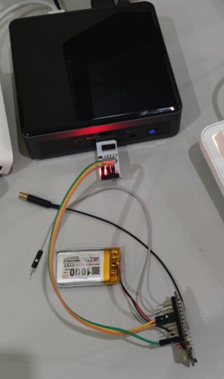
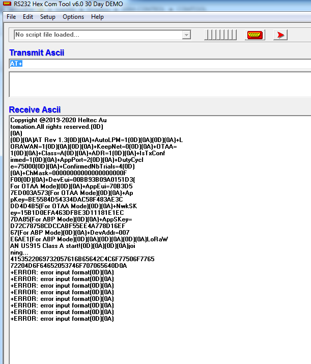
Hello thanks for being interested in my topic, connect a 4.7k pull up resistor and nothing happened, change to 1k and it started working, but it does not recognize any command, to all AT commands it responds: + ERROR: imput format error.
I attach some screenshots
as for the code I am using the LORAWAN example provided in the Arduino IDE
#include "LoRaWan_APP.h"
#include "Arduino.h"

/*
 * set LoraWan_RGB to Active,the RGB active in loraWan
 * RGB red means sending;
 * RGB purple means joined done;
 * RGB blue means RxWindow1;
 * RGB yellow means RxWindow2;
 * RGB green means received done;
 */

/* OTAA para*/
uint8_t devEui[] = { 0x00, 0xBB, 0x93, 0xB0, 0x9A, 0x01, 0x51, 0xD3 };
uint8_t appEui[] = { 0x70, 0xB3, 0xD5, 0x7E, 0xD0, 0x03, 0xA5, 0x73 };
uint8_t appKey[] = { 0xBE, 0x55, 0x84, 0xD5, 0x43, 0x34, 0xDA, 0xC5, 0x8F, 0x48, 0x3A, 0xE3,
0xCD, 0xD4, 0xD4, 0xB5 };

/* ABP para*/
uint8_t nwkSKey[] = { 0x15, 0xb1, 0xd0, 0xef, 0xa4, 0x63, 0xdf, 0xbe, 0x3d, 0x11, 0x18, 0x1e, 0x1e,
0xc7, 0xda,0x85 };
uint8_t appSKey[] = { 0xd7, 0x2c, 0x78, 0x75, 0x8c, 0xdc, 0xca, 0xbf, 0x55, 0xee, 0x4a, 0x77, 0x8d,
0x16, 0xef,0x67 };
uint32_t devAddr =  ( uint32_t )0x007e6ae1;

/*LoraWan channelsmask, default channels 0-7*/
uint16_t userChannelsMask[6]={ 0xFF00,0x0000,0x0000,0x0000,0x0000,0x0000 };

/*LoraWan region, select in arduino IDE tools*/
LoRaMacRegion_t loraWanRegion = ACTIVE_REGION;

/*LoraWan Class, Class A and Class C are supported*/
DeviceClass_t  loraWanClass = LORAWAN_CLASS;

/*the application data transmission duty cycle.  value in [ms].*/
uint32_t appTxDutyCycle = 15000;

/*OTAA or ABP*/
bool overTheAirActivation = LORAWAN_NETMODE;

/*ADR enable*/
bool loraWanAdr = LORAWAN_ADR;

/* set LORAWAN_Net_Reserve ON, the node could save the network info to flash, when node reset
not need to join again */
bool keepNet = LORAWAN_NET_RESERVE;

/* Indicates if the node is sending confirmed or unconfirmed messages */
bool isTxConfirmed = LORAWAN_UPLINKMODE;

/* Application port */
uint8_t appPort = 2;
/*!
* Number of trials to transmit the frame, if the LoRaMAC layer did not
* receive an acknowledgment. The MAC performs a datarate adaptation,
* according to the LoRaWAN Specification V1.0.2, chapter 18.4, according
* to the following table:
*
* Transmission nb | Data Rate
* ----------------|-----------
* 1 (first)       | DR
* 2               | DR
* 3               | max(DR-1,0)
* 4               | max(DR-1,0)
* 5               | max(DR-2,0)
* 6               | max(DR-2,0)
* 7               | max(DR-3,0)
* 8               | max(DR-3,0)
*
* Note, that if NbTrials is set to 1 or 2, the MAC will not decrease
* the datarate, in case the LoRaMAC layer did not receive an acknowledgment
*/
uint8_t confirmedNbTrials = 4;

/* Prepares the payload of the frame */
static void prepareTxFrame( uint8_t port )
{
/*appData size is LORAWAN_APP_DATA_MAX_SIZE which is defined in "commissioning.h".
*appDataSize max value is LORAWAN_APP_DATA_MAX_SIZE.
*if enabled AT, don't modify LORAWAN_APP_DATA_MAX_SIZE, it may cause system hanging or
failure.
*if disabled AT, LORAWAN_APP_DATA_MAX_SIZE can be modified, the max value is reference
to lorawan region and SF.
*for example, if use REGION_CN470,
*the max value for different DR can be found in MaxPayloadOfDatarateCN470 refer to
DataratesCN470 and BandwidthsCN470 in "RegionCN470.h".
*/
appDataSize = 4;
appData[0] = 0x00;
appData[1] = 0x01;
appData[2] = 0x02;
appData[3] = 0x03;
}


void setup() {
Serial.begin(115200);
#if(AT_SUPPORT)
enableAt();
#endif
deviceState = DEVICE_STATE_INIT;
LoRaWAN.ifskipjoin();
}

void loop()
{
switch( deviceState )
{
	case DEVICE_STATE_INIT:
	{
#if(LORAWAN_DEVEUI_AUTO)
		LoRaWAN.generateDeveuiByChipID();
#endif
#if(AT_SUPPORT)
		getDevParam();
#endif
		printDevParam();
		LoRaWAN.init(loraWanClass,loraWanRegion);
		deviceState = DEVICE_STATE_JOIN;
		break;
	}
	case DEVICE_STATE_JOIN:
	{
		LoRaWAN.join();
		break;
	}
	case DEVICE_STATE_SEND:
	{
		prepareTxFrame( appPort );
		LoRaWAN.send();
		deviceState = DEVICE_STATE_CYCLE;
		break;
	}
	case DEVICE_STATE_CYCLE:
	{
		// Schedule next packet transmission
		txDutyCycleTime = appTxDutyCycle + randr( 0, APP_TX_DUTYCYCLE_RND );
		LoRaWAN.cycle(txDutyCycleTime);
		deviceState = DEVICE_STATE_SLEEP;
		break;
	}
	case DEVICE_STATE_SLEEP:
	{
		LoRaWAN.sleep();
		break;
	}
	default:
	{
		deviceState = DEVICE_STATE_INIT;
		break;
	}
}
}
the configuration is this