Questions about Wifi LoRa V2 Pinout diagram

Maybe i’m too unexperienced with the Wifi LoRa 32 (V2), but there are a few questions about its pinout diagram, i can’t explain.

Which pin is able to work as a interrupt pin?

Where do I connect my power supply to the Wifi LoRa V2 board? Generally, these are the pins marked with V_DD, V_IN or similar to that. But at the Wifi LoRa V2, there are “voltage” pins which just provide voltage seemingly. However, I wasn’t able to extract this information neither from the pinout diagramm nor from the schema.

Which voltage/current does the Wifi LoRa V2 board provide at the GPIO pins? Which current does the Wifi LoRa V2 board provide at the 3V3, 5V output source?

In collecting information to this topic, somebody talked about pin multiplexing. Due to the fact that I never worked with a ESP32 before, an explanation what pin multiplexing is, would be very helpful.

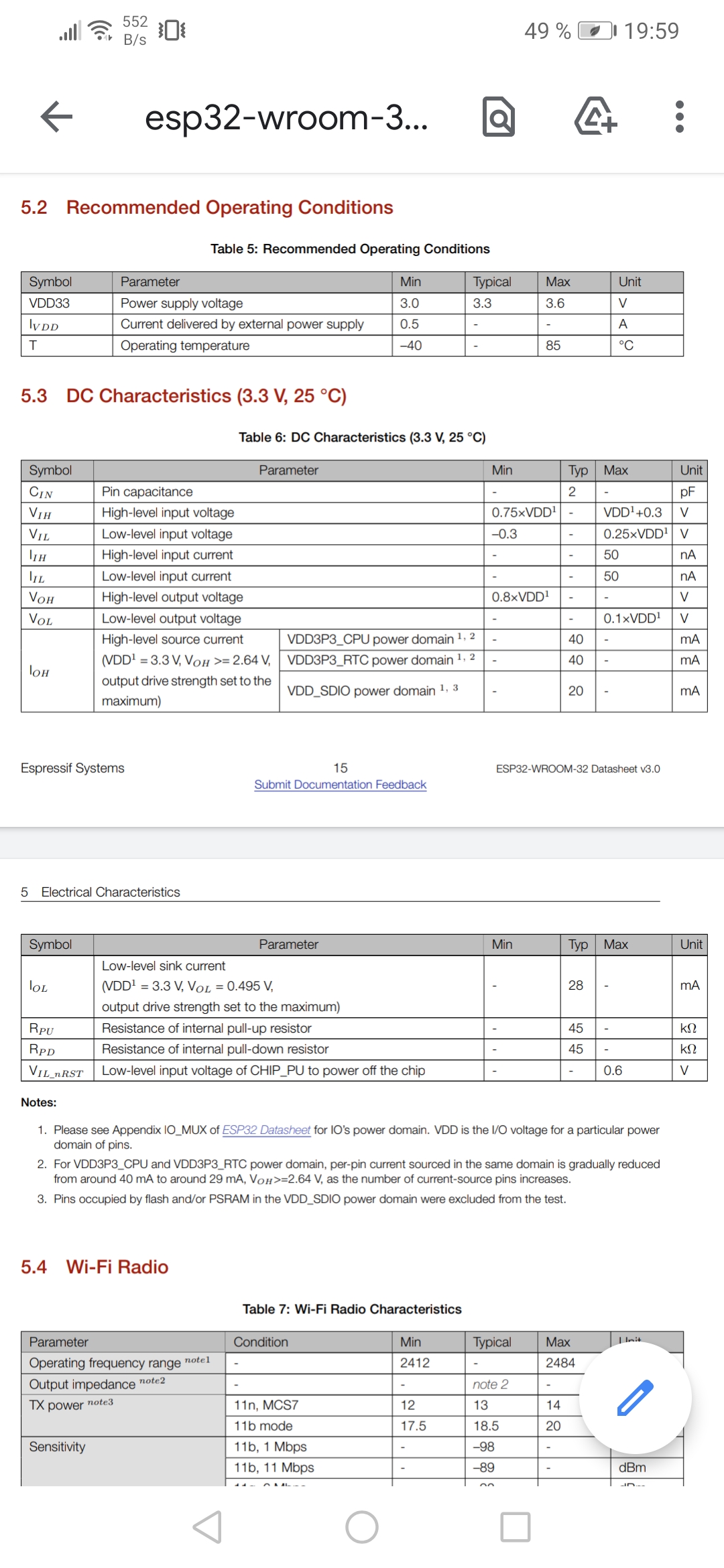
It would also be very helpful, if somebody could give me a complete datasheet. Maybe thats the cause why I ask so many greenhorn questions :wink:

Many thanks in advance to the person who is able to help me.

Does anybody else has this problem?
Actually, I thought that somebody should be able to help me.

You can connect an Lipo Battery to to the connector of the board (3,7V). Or 3.3 directly to 3,3V or USB power.
Please have a look too.
https://heltec-automation-docs.readthedocs.io/en/latest/esp32/wifi_lora_32/hardware_update_log.html.
You can drive current see picture below each io

Thank you @OMatthias
Can I then just use the 3.3 V pin as VDD or is it able to use the 5 V pin as VDD too, because USB power would also be about 5 V VDD?

Does anybody know, which pins can get used as interrupt pins? Or is it able to use every digital pin as an interrupt pin at the Wifi LoRa 32 (V2) ?

@johfl144 please have a look to the pinout here
https://heltec-automation-docs.readthedocs.io/en/latest/esp32/wifi_lora_32/hardware_update_log.html
When your question should be answered. We have 3v3 pins and 5v pins. So please be sure that you connect the right voltage to the pins.
Also here you can see which pins are free for use. Not all are! You should reading more before asking questions.

@OMatthias
Thank you very much that you want to help.
I had multiple looks on the pinout of your links even before you answered me. I researched a lot before asking this question. But I didn’t find any hints to get to know something about interrupt pins of this board. Normally, at the pinout diagram, there are pin nominations like VDD (V_in) or something. Thereby, I know definitely, where the voltage source is and where output sources are. Even at a normal pinout diagram, there are pins marked as interrupt pins or I can read it at a data sheet. That’s not the case here and after multiple looks on the website you linked, I couldn’t find something about this topic.
If you or somebody else have experience with this board and is able to help me, I would be very thankful, but linking the same page a few times or expostulating me, doesn’t help me on.

Se here many examples for this board also for external wake up (interrupt).
I think also my data sheet about wroom32 helps to find out the interrupt pins.
Also you can search for general esp32 documents for using interrupt and so. If I have more time I can post.

To Vin and out. Have look the schematic to understand it it is included.