
Hello everyone, I am working with the custom examples of heltec esp32 Dev-Boards, Led_control_S and Led_control_R. without altering them, on my lora 32 v3 wifi plates. According to the serial monitor, everything is correct, but the LED does not light up when receiving the Open Led command. I have changed the output from GPIO 35, to GPIO 7, to 47,… what could it be? Thank you
Problems with heltec esp32 Dev-Boards, Led_control_S and Led_control_R
You might need to provide more information—I can’t see any sketches named Led_control_S or Led_control_R in the Arduino IDE examples for the WiFi LoRa 32 V3 board…
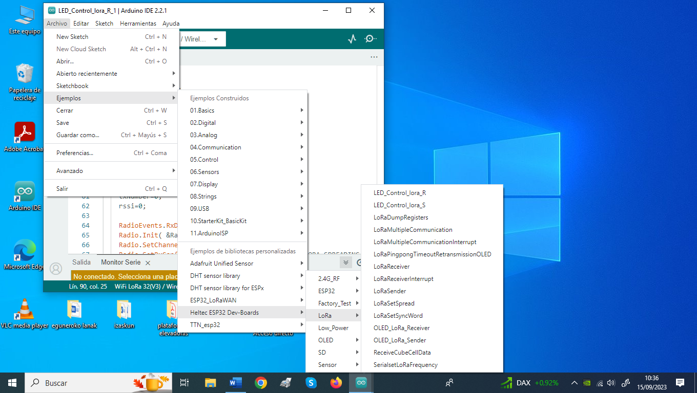
I sent you a screenshot and the original codes.
/*
Send a lora signal to control the LED light switch of another board.
Pull the 12th pin high to turn on the LED light.
Pull pin 13 high to turn off the LED light.
by Aaron.Lee from HelTec AutoMation, ChengDu, China
成都惠利特自动化科技有限公司
this project also realess in GitHub:
https://github.com/Heltec-Aaron-Lee/WiFi_Kit_series
*/
#include “LoRaWan_APP.h”
#include “Arduino.h”
#define RF_FREQUENCY 915000000 // Hz
#define TX_OUTPUT_POWER 5 // dBm
#define LORA_BANDWIDTH 0 // [0: 125 kHz,
                                                          //  1: 250 kHz,

                                                          //  2: 500 kHz,

                                                          //  3: Reserved]
#define LORA_SPREADING_FACTOR 7 // [SF7…SF12]
#define LORA_CODINGRATE 1 // [1: 4/5,
                                                          //  2: 4/6,

                                                          //  3: 4/7,

                                                          //  4: 4/8]
#define LORA_PREAMBLE_LENGTH 8 // Same for Tx and Rx
#define LORA_SYMBOL_TIMEOUT 0 // Symbols
#define LORA_FIX_LENGTH_PAYLOAD_ON false
#define LORA_IQ_INVERSION_ON false
#define RX_TIMEOUT_VALUE 1000
#define BUFFER_SIZE 30 // Define the payload size here
char txpacket[BUFFER_SIZE];
char rxpacket[BUFFER_SIZE];
double txNumber;
bool lora_idle=true;
static RadioEvents_t RadioEvents;
void OnTxDone( void );
void OnTxTimeout( void );
int counter = 0;
#define Open_LED 12
#define Close_LED 13
void setup() {
//WIFI Kit series V1 not support Vext control
Serial.begin(115200);
Mcu.begin();


txNumber=0;

RadioEvents.TxDone = OnTxDone;

RadioEvents.TxTimeout = OnTxTimeout;


Radio.Init( &RadioEvents );

Radio.SetChannel( RF_FREQUENCY );

Radio.SetTxConfig( MODEM_LORA, TX_OUTPUT_POWER, 0, LORA_BANDWIDTH,

                               LORA_SPREADING_FACTOR, LORA_CODINGRATE,

                               LORA_PREAMBLE_LENGTH, LORA_FIX_LENGTH_PAYLOAD_ON,

                               true, 0, 0, LORA_IQ_INVERSION_ON, 3000 );
pinMode(Open_LED,INPUT);
digitalWrite(Open_LED,LOW);
pinMode(Close_LED,INPUT);
digitalWrite(Close_LED,LOW);
// LoRa.setTxPower(14,RF_PACONFIG_PASELECT_PABOOST);
}
void loop() {
if(digitalRead(Open_LED)){
Serial.print("Sending packet: OpenLED\r\n");

// send packet

 if(lora_idle == true)
{
delay(1000);

txNumber += 0.01;

sprintf(txpacket,"OpenLED %0.2f",txNumber);  //start a package


Serial.printf("\r\nsending packet \"%s\" , length %d\r\n",txpacket, strlen(txpacket));

Radio.Send( (uint8_t *)txpacket, strlen(txpacket) ); //send the package out

lora_idle = false;
}
Radio.IrqProcess( );
digitalWrite(Open_LED,LOW);
}
if(digitalRead(Close_LED)){
Serial.print("Sending packet: CloseLED\r\n");

// send packet
if(lora_idle == true)
{
delay(1000);

txNumber += 0.01;

sprintf(txpacket,"CloseLED %0.2f",txNumber);  //start a package


Serial.printf("\r\nsending packet \"%s\" , length %d\r\n",txpacket, strlen(txpacket));

Radio.Send( (uint8_t *)txpacket, strlen(txpacket) ); //send the package out

lora_idle = false;
}
Radio.IrqProcess( );
digitalWrite(Close_LED,LOW);
}
delay(1000);
}
void OnTxDone( void )
{
Serial.println(“TX done…”);
lora_idle = true;
}
void OnTxTimeout( void )
{
Radio.Sleep( );

Serial.println("TX Timeout......");

lora_idle = true;
}
/*
Receive the lora signal to control the on and off of the LED.
Pull the 12th pin high to turn on the LED light.
Pull pin 13 high to turn off the LED light.
by Aaron.Lee from HelTec AutoMation, ChengDu, China
成都惠利特自动化科技有限公司
this project also realess in GitHub:
https://github.com/Heltec-Aaron-Lee/WiFi_Kit_series
*/
#include “string.h”
#include “stdio.h”
#include “LoRaWan_APP.h”
#include “Arduino.h”
#define RF_FREQUENCY 915000000 // Hz
#define TX_OUTPUT_POWER 14 // dBm
#define LORA_BANDWIDTH 0 // [0: 125 kHz,
                                                          //  1: 250 kHz,

                                                          //  2: 500 kHz,

                                                          //  3: Reserved]
#define LORA_SPREADING_FACTOR 7 // [SF7…SF12]
#define LORA_CODINGRATE 1 // [1: 4/5,
                                                          //  2: 4/6,

                                                          //  3: 4/7,

                                                          //  4: 4/8]
#define LORA_PREAMBLE_LENGTH 8 // Same for Tx and Rx
#define LORA_SYMBOL_TIMEOUT 0 // Symbols
#define LORA_FIX_LENGTH_PAYLOAD_ON false
#define LORA_IQ_INVERSION_ON false
#define RX_TIMEOUT_VALUE 1000
#define BUFFER_SIZE 30 // Define the payload size here
char txpacket[BUFFER_SIZE];
char rxpacket[BUFFER_SIZE];
static RadioEvents_t RadioEvents;
int16_t txNumber;
int16_t rssi,rxSize;
bool lora_idle = true;
#define LED 35
char Readback[50];
void setup() {
//WIFI Kit series V1 not support Vext control
Serial.begin(115200);
Mcu.begin();


txNumber=0;

rssi=0;


RadioEvents.RxDone = OnRxDone;

Radio.Init( &RadioEvents );

Radio.SetChannel( RF_FREQUENCY );

Radio.SetRxConfig( MODEM_LORA, LORA_BANDWIDTH, LORA_SPREADING_FACTOR,

                           LORA_CODINGRATE, 0, LORA_PREAMBLE_LENGTH,

                           LORA_SYMBOL_TIMEOUT, LORA_FIX_LENGTH_PAYLOAD_ON,

                           0, true, 0, 0, LORA_IQ_INVERSION_ON, true );
pinMode(LED,OUTPUT);
digitalWrite(LED,LOW);
}
void loop() {
// try to parse packet
if(lora_idle)
{
lora_idle = false;

Serial.println("into RX mode");

Radio.Rx(0);
}
Radio.IrqProcess();
}
void OnRxDone( uint8_t *payload, uint16_t size, int16_t rssi, int8_t snr )
{
rssi=rssi;

rxSize=size;

memcpy(rxpacket, payload, size );

rxpacket[size]='\0';

Radio.Sleep( );

Serial.printf("\r\nreceived packet \"%s\" with rssi %d , length %d\r\n",rxpacket,rssi,rxSize);

lora_idle = true;
if(strncmp(rxpacket, “OpenLED”, strlen(rxpacket)) == 0) {
digitalWrite(LED, HIGH);
}
else if(strncmp(rxpacket, “CloseLED”, strlen(rxpacket)) == 0) {
digitalWrite(LED, LOW);
}
}
Yeah, OK, you’re running a later software revision than I am (and I’m not keen to change anything in my set-up at the moment because everything is working and I have other things to do). But there’s nothing in there that jumps out as being obviously problematic.
All I could suggest is inserting some extra print statements in there to verify that the condition statements that turn the LED ON and OFF are actually executed. Maybe also check that the LED turns ON and OFF with a ‘local’ sketch that doesn’t depend on the message being sent between the two modules. If that all checks out, then maybe the problem is in the way the ‘message’ is constructed or interpreted.
I use a more formal packet structure in my LoRa applications but I have no trouble sending various instructions, to perform a range of tasks, between LoRa nodes.