
In my project I am using an I2C compatible SI1145 light sensor connected to pin 21 ( SDA ) and pin 22 ( SCL ) of the WiFi Kit 32 board. The sensor functions normally, and correct data can be read from it, and displayed using the Arduino serial monitor at 9600Bd.
But when I also use the in-built OLED, there is now NO data and NO clock on pins 21 and 22 ( checked with a logic analyser ). So there is no communication with the sensor, and NO data can be read, although the OLED display appears to be functioning correctly displaying just the text, but the “sensor value” is nonsense, ( also on serial monitor if 115200Bd ).
It is my understanding that the OLED display and sensor are on separate I2C busses, because the ESP32 has two I2C busses. So what is going on ?
My setup is Arduino IDE 1.8.13, heltec.h library included in my code, OLED I2C0 0x3C, sensor I2C1 0x60.
In summary, the OLED and sensor when used individually and separately function normally. But when both are connected ( separate I2C busses ) only the OLED functions correctly.
Does anyone have the solution ?
Problem with WiFi Kit 32 & I2C
If you want to use two sets of I2C, you need to initialize the two sets of I2C separately, such as Wire.begin(), Wire1.begin(). Or you can connect two I2C devices to a set of I2C interfaces.
Thanks, and I have used the commands you proposed in my sketch, but this alone did not result in a solution to the problem.
I have found that if I just comment out the following line of code:-
Heltec.begin(true, false, true);
my sensor immediately functions correctly and valid data can be read on the serial monitor though not on the OLED of course. ( Heltec.h library is still included as are other heltec display commands ).
Does this suggest that there is a conflict between the heltec.h library and the sensor library ? Should the library be edited in some way ? Can another library be used to drive the OLED ? For example a SSD1306 compatible library, possibly one from Adafruit ?
Could the sensor be connected to the same I2C0 bus as the OLED ?
Has anyone successfully used a second I2C device as well as the built-in OLED in the same sketch/project on the WiFi Kit 32 ( HTIT-WB32 ) board.
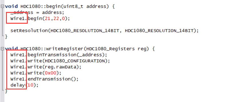
If you use Wire1.begin(), you need to replace all Wire.*** of the second set of I2C with Wire1.***, and you can set the SDA, SCL pins and frequency in Wire1.begin(). For example
The easiest way is to use the same set of I2C pins for the OLED and the sensor
It was always on my list of things to try and as I have exhausted all other possibilities without finding a solution, as a last resort I have now connected the sensor to the same bus I2C0 ( Wire.begin(4, 15, 100000) SDA=4, SCL=15 ) as the built-in OLED display. Now both devices are functioning together correctly. From the start of my project, I had hoped to avoid doing this by using separate buses as there are two, namely I2C0 & I2C1; but it seems that in my project this is not going to be possible. I have no explanation why this should be necessary !
@Spacerowa – thanks for your detailed explanation for how to address this; I was at a total loss up until then.
for anyone else who finds themselves in the same boat, I modified the I2C scanner sketch using SDA=4, SCL=15:
// this I2C scanning utility is specifically for the Heltec ESP32 OLED board
// for all intents and purposes, the Heltec ESP32 OLED board only has one I2C bus (I2C0).
// the built-in OLED display on I2C0 uses address 0x3C.
// other I2C peripherals (clock 7-seg display, LCD 16x2 display) should be attached to
//   GPIO4 (SDA) and GPIO15 (SCL). disregard the usage warning in the device's pinout


#include "Arduino.h"
#include "heltec.h"


void setup() {
  Serial.begin(115200);
  Heltec.begin(true, false, true);
  Wire.begin(4, 15, 100000); // SDA=4, SCL=15
}


void loop() {
  byte error, address;
  int nDevices = 0;

  Serial.println("\nScanning...");

  for (address = 1; address < 127; address++) {
    Wire.beginTransmission(address);
    error = Wire.endTransmission();

    if (error == 0) {
      Serial.print("I2C device found at address 0x");

      if (address < 16) {
        Serial.print("0");
      }

      if (address == 60) {
        Serial.print(address, HEX);
        Serial.println(" (this is the built-in OLED display)");
      } else {
        Serial.println(address, HEX);
      }
      nDevices++;

    } else if (error == 4) {
      Serial.print("Unknown error at address 0x");

      if (address < 16) {
        Serial.print("0");
      }
      Serial.println(address, HEX);
    }
  }

  if (nDevices == 0) {
    Serial.println("No I2C devices found.");
    Serial.println("Ensure the peripheral's SDA is connected to GPIO4 and");
    Serial.println("Ensure the peripheral's SCL is connected to GPI015.");
  } else {
    Serial.println("Done.");
  }

  delay(5000);
}hi , i have the same problem but in other way i’m coding a arduino slave send data to heltec wireless stick
I have found that if i just comment out the following line of code:-
—> Heltec.begin(true , true , true, true , BAND ); the data recivet correctly any helpe thank you
Blockquote
#include"Arduino.h"
#include “heltec.h”
//#include <Wire.h>
#define BAND 868E6 //you can set band here directly,e.g. 868E6,915E6
void setup()
{
Serial.begin(9600);
Wire.begin(21,22,100000); // join i2c bus
//WIFI Kit series V1 not support Vext control
//Heltec.begin(true /DisplayEnable Enable/, true /Heltec.LoRa Disable/, true /Serial Enable/, true /PABOOST Enable/, BAND /long BAND/);
}
void loop() {
Wire.requestFrom(4,1);
while(Wire.available())
{
//char c =Wire.read();
//Serial.print©;
int x =Wire.read();
Serial.println(x);
/*  LoRa.beginPacket();
  LoRa.setTxPower(14,RF_PACONFIG_PASELECT_PABOOST);
  LoRa.print(x);
  LoRa.endPacket();*/
}
delay(500);
}