Need help identifying what microcontroller this is

can I refer to this documentation:" HTIT-WiFi kit32_V3(Rev1.1).pdf (heltec.cn)"

I am not sure as the device shown in the documentation is exactly the same if you can notice in picture 1 under the v3 there is v3.1.
If possible could the reply also include some documentation on how to connect it to gateways like how i can generate dev eui and appkey?

I am a new user so I can only post one image this is the other one:
[HTIT-WiFi kit32_V3(Rev1.1).pdf (heltec.cn)](https://resource.heltec.cn/download/WiFi_Kit_32_V3/HTIT-

Also on another note, which of this pins are PWM pins using this? I am not sure if this is correct

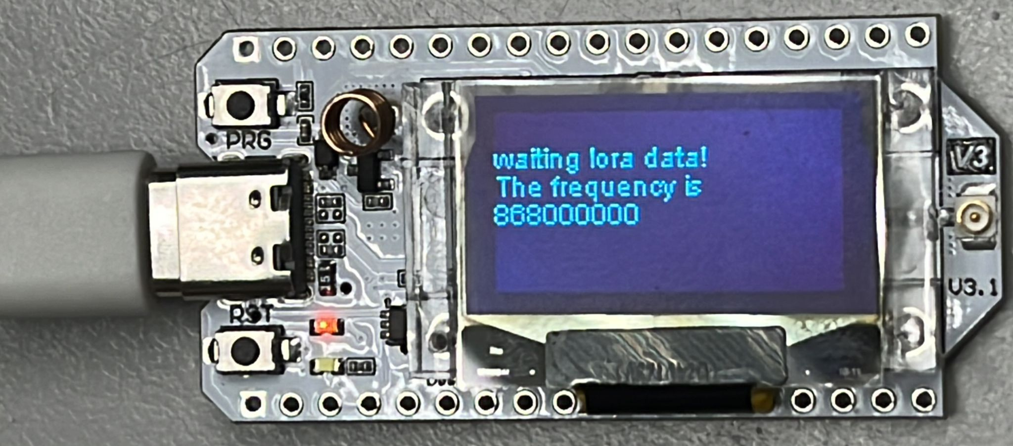
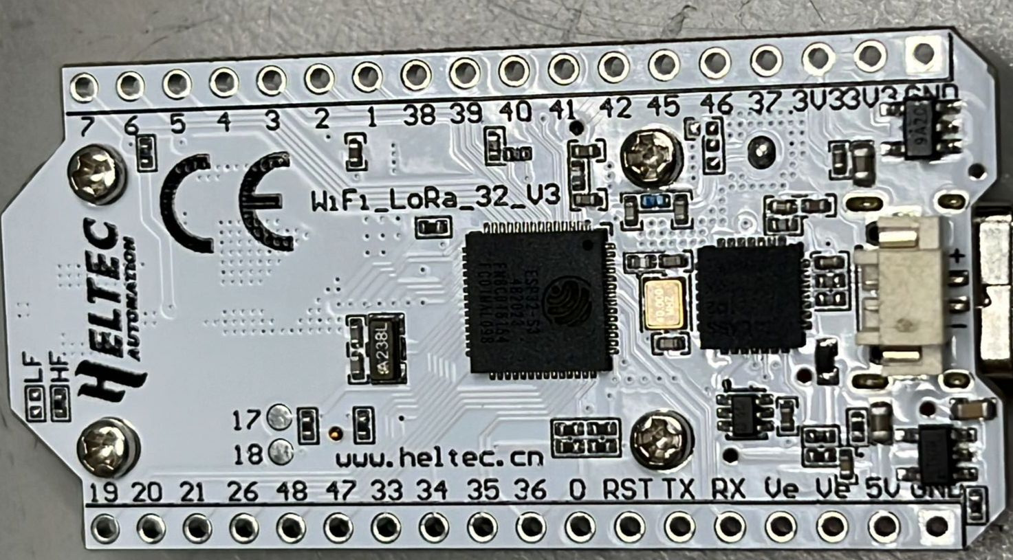
Given the print below the LoRa u.FL connector on your first image and the print on the backside of the board, that would be a WiFi LoRa 32 V3.1 or in other terms V3 (1.1).
The relevant documents can be found here, as long as you pick any .1 version.

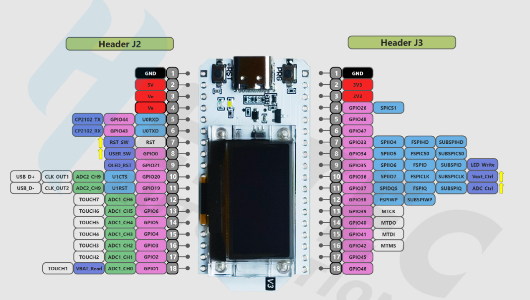
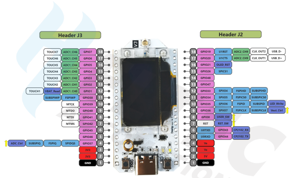
Regarding PWM: the ESP32-S3 can drive up to 8 PWM pins on any pin that is output-capable which are all of the listed pins, as long as you make sure they’re not already in use for something else.

Regarding LoRaWAN: I recommend using RadioLib. To get a DevEUI, you can let TTN generate one for you to be sure, I’m not competely sure the Heltec-provided EUIs are officially unique.
Alternatively, you can flash the following sketch, which is based on Heltec’s package (newest version whatever it is). It will print out the ChipID which you must input on Heltec’s website, and in turn that will give you a license which you can copy straight into the serial monitor, press enter and it will print out a DevEUI for you.

#include "LoRaWan_APP.h"

uint32_t license[4]={ 0 };

// these keys are random stuff, no need to change them for this sketch
/* OTAA para*/
uint8_t devEui[] = { 0x22, 0x32, 0x33, 0x00, 0x00, 0x88, 0x88, 0x02 };
uint8_t appEui[] = { 0x00, 0x00, 0x00, 0x00, 0x00, 0x00, 0x00, 0x00 };
uint8_t appKey[] = { 0x88, 0x88, 0x88, 0x88, 0x88, 0x88, 0x88, 0x88, 0x88, 0x88, 0x88, 0x88, 0x88, 0x88, 0x88, 0x88 };

/* ABP para*/
uint8_t nwkSKey[] = { 0x15, 0xb1, 0xd0, 0xef, 0xa4, 0x63, 0xdf, 0xbe, 0x3d, 0x11, 0x18, 0x1e, 0x1e, 0xc7, 0xda,0x85 };
uint8_t appSKey[] = { 0xd7, 0x2c, 0x78, 0x75, 0x8c, 0xdc, 0xca, 0xbf, 0x55, 0xee, 0x4a, 0x77, 0x8d, 0x16, 0xef,0x67 };
uint32_t devAddr =  ( uint32_t )0x007e6ae1;

/*LoraWan channelsmask, default channels 0-7*/ 
uint16_t userChannelsMask[6]={ 0x00FF,0x0000,0x0000,0x0000,0x0000,0x0000 };

LoRaMacRegion_t loraWanRegion = ACTIVE_REGION;
DeviceClass_t  loraWanClass = CLASS_A;
uint32_t appTxDutyCycle = 150000;
bool overTheAirActivation = true;
bool loraWanAdr = true;
bool isTxConfirmed = true;
uint8_t appPort = 2;
uint8_t confirmedNbTrials = 4;

void parseLicense(String input) {
  int start = 0;
  int end = input.indexOf(',');

  for (int i = 0; i < 4; i++) {
    if (end == -1) {
      end = input.length();
    }
    String hexString = input.substring(start, end);
    license[i] = strtoul(hexString.c_str(), NULL, 16);
    start = end + 1;
    end = input.indexOf(',', start);
  }
}

void setup() {
  Serial.begin(115200);
  
  uint64_t chipId = ESP.getEfuseMac();
  Serial.printf("%04X",(uint16_t)(chipId>>32));//print High 2bytes
  Serial.printf("%08X\r\n",(uint32_t)chipId);//print Low 4bytes.

  while(!Serial.available());
  String input = Serial.readStringUntil('\n');
  parseLicense(input);

  Mcu.setlicense(license,HELTEC_BOARD);
  Mcu.begin(HELTEC_BOARD,SLOW_CLK_TPYE);
  LoRaWAN.generateDeveuiByChipID();
  for(int i = 0; i < 8; i++) {
    Serial.printf("%02X", devEui[i]);
  }

}

void loop() {

}

You don’t need to change anything for that sketch, they are just some remnants from the usual examples that are required to compile but not used.

Hi, for my project as of right now, I only need 4 pins, 2 PWM and 2 GPIO pins, 2 PWM is for servo motor. Ideally I want the servo motor to be able to life an object like a bridge(laser cut square acrylic). and the other 2 pins is used for ultrasonic ranger trig and echo pin. As for the connection I am just planning to connect it via lora to a gateway. I was just wondering if this is feasible I just want to get some feedback. And also I would like to ask: “I’m not super clear but shouldn’t lora integration file tutorial on arduino ide have dev eui and appkey generator?”

This is a Heltec forum where you may get advise from random strangers about Heltec products and software, not about the feasability of building laser cutters lol. No clue if that’s doable. But I can advise you that you may not be able to use LoRaWAN to do any kind of fancy laser cutting because you can’t transfer any reasonable amount of data using LW.
Nor am I able to do anything about Heltec’s stupid DevEUI shenanigans which I wish I could. But DevEUI is linked to a device, you’re not supposed to have multiple and I gave you the solution to that. Keys are usually generated on whatever LoRaWAN network server you use (TTN, Chirpstack, …).

no no I am not planning on building a laser cutter. I am planning on using the laser cutter to cut a piece of acrylic to use the servo motor to lift it up.
I am using chirpstack as my network server however I have only ever used the preset dev eui and app key from adding other devices to chirpstack but I am a little unclear on the creation of dev eui and appkey and how chirpstack is supposed to help with that.

Regarding the creation of DevEUI: I gave you the steps and sketch two messages ago. Regarding the AppKey: I don’t know, ask on the Chirpstack forum or read their docs.

The MCU is an ESP32-S3. Also, that board does not have a LoRa radio. Their best bet for LoRa is the Wireless Stick board.

Part of the problem here might be that, as someone new to Heltec products, @ziyor is confusing the WiFi LoRa 32 board with the WiFi Kit 32 (no LoRa radio) board. The photos in the original post are of a WiFi LoRa 32 board, but the pinout diagram subsequently posted appears to be of a WiFi Kit 32 board. The respective pin configurations are quite different.

that’d do it. i recently spent time with their product line setting up ELRS

@UniquePete @davidbitton actually I was able to use the chip ID to find the exact pinout but I am still confused. I used the GPIO 48 and 47 for esp32servo.h-> servo motor arduino example but when I wrote the code and tested it the servo motor doesnt turn 90 like I wanted it to. It turns 3 rotations, so I am not sure if 47 and 48 can be used as PWM pins. May I know which other pins can be used as PWM pins?
image

code for testing:
#include “Arduino.h”
#include <Wire.h>
#include <Servo.h>

Servo servo1; // Create a Servo object for the first servo
Servo servo2; // Create a Servo object for the second servo

// Define the GPIO pins for the servos
const int servoPin1 = 47;
const int servoPin2 = 48;

// Define the delay between movements
const int delayTime = 500; // 500 milliseconds

void setup() {
// Start serial communication
Serial.begin(115200);

// Attach the Servo objects to the GPIO pins
servo1.attach(servoPin1);
servo2.attach(servoPin2);

// Set the initial position of the servos
servo1.write(0);
servo2.write(0);

Serial.println(“Servo 1 and Servo 2 initialized at 0 degrees.”);
}

void loop() {
// Rotate the servos to 90 degrees
servo1.write(90);
Serial.println(“Servo 1 rotated to 90 degrees.”);

servo2.write(90);
Serial.println(“Servo 2 rotated to 90 degrees.”);

// Wait for the delay time
delay(delayTime);

// Rotate the servos back to 0 degrees
servo1.write(0);
Serial.println(“Servo 1 rotated back to 0 degrees.”);

servo2.write(0);
Serial.println(“Servo 2 rotated back to 0 degrees.”);

// Wait for the delay time
delay(delayTime);
}

To the best of my knowledge, any output pin can be used as a PWM pin, restrictions on strapping pins notwithstanding. I would have thought 47 & 48 would be OK, but if you want to rule out the possibility that they’re the problem, try with a couple of pins in the range GPIO2-GPIO7. I’ve not used the Servo.h library, so I really can’t offer any other comment than to maybe have a closer look at how that is meant to work.

For servo motor I have understood that although I can use the example, as the programming is similiar I have to use different header files for example esp32servo.h but the thing is myservo motor SG90 keeps spinning 3 rounds when i only want it to rotate 90 degrees if you know anyone who is familiar with servo motor or if anyone reading this have experience using esp32 microcontroller with servo motor hope you can help me. thanks in advance

Is it just a scaling issue? If you enter 7.5, does it turn 90° then? Or when you enter 180°, does it turn 6 times?

i input 90 and it rotates 3 full circles

That was not what @UniquePete suggested. What happens when you input one of his suggested numbers?

Ah I see, I will do that. It seems I misunderstood

just curious how would you deal with could not open com3 the port doesnt exist?