Missing Documentation

Most of the links to documentation for the Heltec WiFi kit 32 v3 go to this page:

“404 Documentation page not found
docs.heltec.org
The documentation page you requested does not exist or may have been removed.
Hosted by Read the Docs logo”

The pinout docs, circuit diagram and pinout diagram do not agree with each other. It is a nightmare trying to get information about this device. After a week of trying to connect a sensor via I2C, a very simple task with ESP32, Arduino etc., I am about to give up and throw the Heltec WiFi kit 32 v3 in the bin!

Hello, we apologize for the unpleasant experience you had. I have just checked the document link and it is functioning properly. The link provides detailed instructions on how to use the product. If you have any questions, please feel free to contact us.

That documentation on that link is for the LoRa product, I am looking for documentation for the Heltec WiFi kit 32 v3. The documentation for the WiFi Kit 32 on that site is non-existant, No pinout diagram, no circuit diagram etc and if you follow the link to the I2C examples you come to " 404 - page not found
The master branch of Heltec_ESP32 does not contain the path
examples/ESP32/I2C1_Scanner/I2C1_Scanner.ino."

Hello friend, this link provides the manual, schematic, and pin diagram for WiFi Kit 32.

Thank you, friend, that is useful. Heltec just need to update and fix a few links.

Best you tell them where you found that broken link then!

The docs șite has links to the resources section, so highly recommend you bookmark that one as that site seems faster than the main sales site.

Best you tell them where you found that broken link then!

I did in my post #3 above.

The docs șite has links to the resources section, so highly recommend you bookmark that one as that site seems faster than the main sales site

What docs site are you refering to? The one at https://docs.heltec.org/en/node/esp32/wifi_kit_32/index.html has almost no information other than how to set up the Arduino IDE

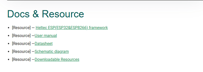
Dear friend, all documentation for our product can be found on the product details page of our official website.

Could you please include a real link to that page, which you have only included a .png of? This is another example of how difficult it is to access useful information from Heltec. Where is the product details page of your official website? Why not give a link rather than a picture of a link?

On the 6th Jan the four links present were working and since then a link to the user manual has been added, all currently working.

Thanks, the other links are useful but the User Manual is very disappointing, it doesn’t offer any WiFi DevKit specific information other than other than how to set up the Arduino IDE. In the Frequently Asked Questions page (which is actually a LoRa v3 FAQ) if you scroll down to " Another Communication Bus Usage Example" and click on either of the I2C examples (I2C0/I2C1) (earlier a special interest of mine, which I’ve solved after several hours of research) you still come to a “404 - page not found” as I pointed out in my OP and in post #3 above.

Both the link and the heading say it is a ESP32 FAQ - for me the usage of a + doesn’t imply much. I’d always scan through the headings to see if there is anything relevant.

The I2C link is https://github.com/HelTecAutomation/Heltec_ESP32/blob/master/examples/ESP32/I2C1_Scanner/I2C1_Scanner.ino which is 404, go up a level, 404, go up a level there is I2C_Scanner: https://github.com/HelTecAutomation/Heltec_ESP32/tree/master/examples/ESP32/I2C_Scanner

BUT, and it’s a big but, I cannot lie, it doesn’t speak to the pins you can use and having to use a second instance of Wire (ie Wire1) so that you can use the OLED at the same time.

However this sort of muddle comes with the territory - there is an implied expectation that developers have reviewed the MCU’s data sheet (https://www.espressif.com/sites/default/files/documentation/esp32-s3_datasheet_en.pdf), have an understanding of the MCU family’s facility - like how many I2C blocks there are and that interconnect / matrix that allows you to connect any block to any pin (with some minor restrictions).

The ESP32-S3 doc is a mere 84 pages and in quickly looking at it, I see that the block diagram on page 2 shows 4 SPI’s but only one I2C block but page 4 tells us that it has two I2C blocks. So even Espressif can’t get it totally right.

Compare this with https://www.espressif.com/sites/default/files/documentation/esp32-s3_technical_reference_manual_en.pdf which is an eye watering 1,529 pages which Heltec will have referred to when they created the schematic, board & Arduino pin variants file: https://github.com/espressif/arduino-esp32/blob/master/variants/heltec_wifi_kit_32_V3/pins_arduino.h

Looking at the pins_arduino.h is useful to see a whole range of things but also to get some hints - so in this file you can see the I2C default pins and at the bottom of the file you can see that the OLED pins are defined separately which implies the use of two I2C instances.

Having two isn’t so obvious if you come from the original Arduino Uno / Nano world as it only has one and the pins are fixed. This learning is part of the stepping up to the next level.

I typically spend a few hours a week cross-referencing docs & source code for any vendors offerings either before implementation (good) or debugging (a bit late then, aka bad). This is normal, maybe it shouldn’t be, but it’s where we are at.

I have a PCB with the HT-CT62 on it(https://heltec.org/project/ht-ct62/) - the pin combos are a bit restricted but it’s working just fine. I’ve had a few people ask for it to be published - but in doing so I’ve about a week of docs to write - with at least one day explaining the restrictions that come with the pins that are broken out. I’m not going there because of exactly the situation you find yourself in - docs can never be comprehensive enough and I’d end up with a blizzard of issues.

If we buy in the 10’s of thousands, we will probably get a direct line to the developers. If we buy in the 100’s of thousands, we will probably get a Field Application Engineer visiting every fortnight. If we buy in the millions, we will probably get a FAE working full time with us for free whilst we do the development.

TL;DR: When we buy hardware at a fair price, we have to join up some of the dots.

1 Like

To be honest I’m a bit disappointed with the Heltec WiFi Devkit 32. Anything it can do can be achieved with much less stress and time with a ESP32 and an OLED screen. And if you are using a breadboard the ESP32 and OLED screen don’t require much more space than the Heltec WiFi Devkit 32.

Still I’ll press on trying to understand this piece of kit, now I’ve started. So I’ll probably be back with more questions in the furure.

For me, ESP32 WROOM (onboard antenna or uFl) + OLED + power management for 10+ devices, then I’d sort out something myself.

But for a quick win these modules price makes it stupid easy to get going, once you are over the ESP32 hump which then gets you in a good place for the Heltec doc’s.

For the TTN conference I needed a board to show off LW Relay - so we used a WiFi LoRa 32 v3 as it comes with LiPo support - so it was mobile in the conf. hall!

The 84 page data sheet is highly recommended and having the schematic to hand.

Do NOT code until you’ve figured out your connections.

And hopefully @Ashley can get some Wire vs Wire1 additions to the docs because we’ve had a number of topics on this recently so clearly this is catching people out.

And hopefully @Ashley can get some Wire vs Wire1 additions to the docs because we’ve had a number of topics on this recently so clearly this is catching people out.

In case anyone finds it useful, here is my code which uses wire(1) for the sensor and wire() for the OLED:

#include <Adafruit_BMP085.h>
#include <Wire.h>
#include <U8g2lib.h>

float knownAltitude = 436.0;
char temp[50];
char druck[50];
float hPa = 999;

#define PIN_SDA 41
#define PIN_SCL 42
#define Vext 36  // External power control

extern TwoWire Wire1;

U8G2_SSD1306_128X64_NONAME_F_HW_I2C u8g2(U8G2_R0, /* reset=*/U8X8_PIN_NONE, /* clock=*/18, /* data=*/17);

Adafruit_BMP085 bmp;

void setup() {
  Serial.begin(115200);

  pinMode(Vext, OUTPUT);
  digitalWrite(Vext, LOW);  // Enable external power **before I2C initialization**
  delay(500);

      // Initialize Wire for OLED on default Heltec pins (17,18)
      Wire.begin(17, 18);
      u8g2.begin();

      // Initialize Wire1 for BMP180 on custom pins
      Wire1.begin(PIN_SDA, PIN_SCL);

      if (!bmp.begin(0x77, &Wire1)) {
        Serial.println("Could not find a valid BMP085 sensor, check wiring!");
        while (1) {}
      }

      // Display test message
      u8g2.clearBuffer();
      u8g2.setFont(u8g2_font_helvR10_tr);
      const char* text1 = "Steve's Barometer";
      int l1 = u8g2.getStrWidth(text1);
      u8g2.drawStr(64 - (l1 / 2), 15, text1);
      u8g2.drawLine(05, 17, 5+l1, 17);
      u8g2.drawStr(02, 35, "Alt = 436m (Fixed)");
      u8g2.sendBuffer();
    }

    void loop() {
      // Calculate sea-level pressure using the known altitude
      float seaLevelPressure = bmp.readPressure() / pow(1.0 - (knownAltitude / 44330.0), 5.255);

      sprintf(temp, "Temp = % .2f*C", bmp.readTemperature());
      u8g2.drawStr(00, 50, temp);
      sprintf(druck, "Druck = %.0f hPa", seaLevelPressure/100);
      u8g2.drawStr(00, 64, druck);
      u8g2.sendBuffer();

      delay(10000);
    }

As a bit of a laugh, I tried ChatGPT. It had to apologise several times for getting the pins wrong, some of which weren’t even broken out on the board. And some wrong info on which pins had to be avoided so as not to clash with flash & booting.

Eventually I got to some pins that could be used that didn’t clash with the anything but that’s me cross-referencing against the schematic & pin graphic.

Finally I very explicitly asked for some code to run both the OLED and a second I2C bus for a sensor which looks fine to me - quite smart calling the second instance Sensor_I2C.

Only very minor observation with your code is that there is no need to extern the Wire1 - Arduino concatenates all the source code. With PlatformIO you’d need to do that if you wanted to use the Wire1 in a different file but mostly we initialise a sensor by passing a reference to it as is done here with the bmp.begin(). YMMV.

Thanks for the info regarding Extern, I have also discovered that there is no need to define Vext, pinMode(Vext, OUTPUT); is enough. So the sketch is now two lines less.