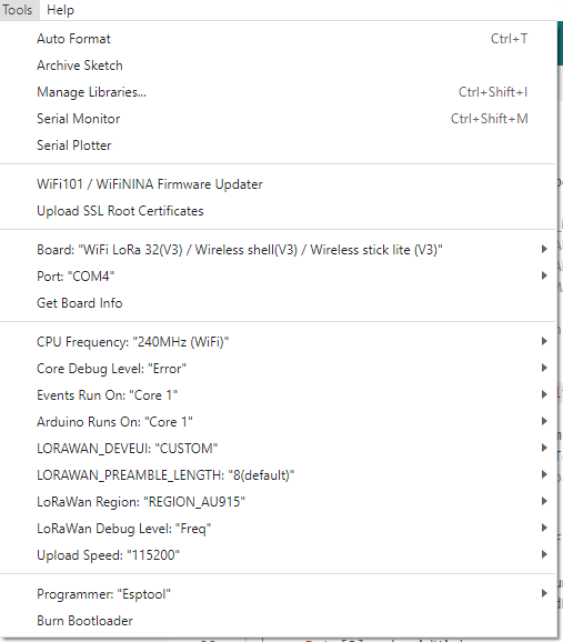
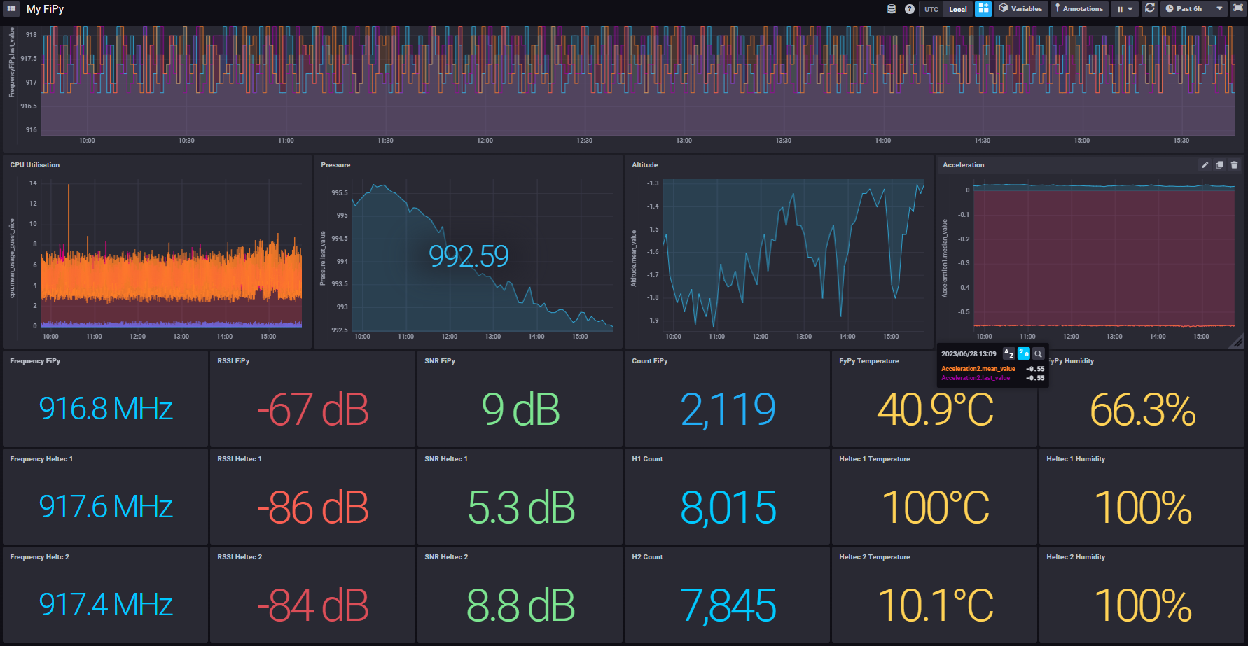
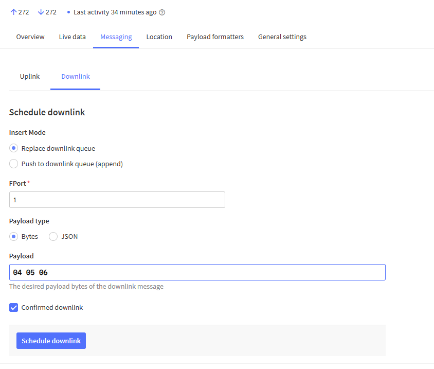
Can someone could help me to understand this sketch and explain me how to receive downlink data :
#include “LoRaWan_APP.h”
/* OTAA para*/
uint8_t devEui[] = { 0x22, 0x32, 0x33, 0x00, 0x00, 0x88, 0x88, 0x02 };
uint8_t appEui[] = { 0x00, 0x00, 0x00, 0x00, 0x00, 0x00, 0x00, 0x00 };
uint8_t appKey[] = { 0x88, 0x88, 0x88, 0x88, 0x88, 0x88, 0x88, 0x88, 0x88, 0x88, 0x88, 0x88, 0x88, 0x88, 0x66, 0x01 };
/* ABP para*/
uint8_t nwkSKey[] = { 0x15, 0xb1, 0xd0, 0xef, 0xa4, 0x63, 0xdf, 0xbe, 0x3d, 0x11, 0x18, 0x1e, 0x1e, 0xc7, 0xda,0x85 };
uint8_t appSKey[] = { 0xd7, 0x2c, 0x78, 0x75, 0x8c, 0xdc, 0xca, 0xbf, 0x55, 0xee, 0x4a, 0x77, 0x8d, 0x16, 0xef,0x67 };
uint32_t devAddr = ( uint32_t )0x007e6ae1;
/LoraWan channelsmask, default channels 0-7/
uint16_t userChannelsMask[6]={ 0x00FF,0x0000,0x0000,0x0000,0x0000,0x0000 };
/LoraWan region, select in arduino IDE tools/
LoRaMacRegion_t loraWanRegion = ACTIVE_REGION;
/LoraWan Class, Class A and Class C are supported/
DeviceClass_t loraWanClass = CLASS_A;
/the application data transmission duty cycle. value in [ms]./
uint32_t appTxDutyCycle = 15000;
/OTAA or ABP/
bool overTheAirActivation = true;
/ADR enable/
bool loraWanAdr = true;
/* Indicates if the node is sending confirmed or unconfirmed messages */
bool isTxConfirmed = true;
/* Application port /
uint8_t appPort = 2;
/!
- Number of trials to transmit the frame, if the LoRaMAC layer did not
- receive an acknowledgment. The MAC performs a datarate adaptation,
- according to the LoRaWAN Specification V1.0.2, chapter 18.4, according
- to the following table:
- Transmission nb | Data Rate
- ----------------|-----------
- 1 (first) | DR
- 2 | DR
- 3 | max(DR-1,0)
- 4 | max(DR-1,0)
- 5 | max(DR-2,0)
- 6 | max(DR-2,0)
- 7 | max(DR-3,0)
- 8 | max(DR-3,0)
- Note, that if NbTrials is set to 1 or 2, the MAC will not decrease
- the datarate, in case the LoRaMAC layer did not receive an acknowledgment
*/
uint8_t confirmedNbTrials = 4;
/* Prepares the payload of the frame */
static void prepareTxFrame( uint8_t port )
{
/*appData size is LORAWAN_APP_DATA_MAX_SIZE which is defined in “commissioning.h”.
*appDataSize max value is LORAWAN_APP_DATA_MAX_SIZE.
*if enabled AT, don’t modify LORAWAN_APP_DATA_MAX_SIZE, it may cause system hanging or failure.
*if disabled AT, LORAWAN_APP_DATA_MAX_SIZE can be modified, the max value is reference to lorawan region and SF.
*for example, if use REGION_CN470,
*the max value for different DR can be found in MaxPayloadOfDatarateCN470 refer to DataratesCN470 and BandwidthsCN470 in “RegionCN470.h”.
*/
appDataSize = 4;
appData[0] = 0x00;
appData[1] = 0x01;
appData[2] = 0x02;
appData[3] = 0x03;
}
//downlink data handle function example
void downLinkDataHandle(McpsIndication_t *mcpsIndication)
{
Serial.printf("+REV DATA:%s,RXSIZE %d,PORT %d\r\n",mcpsIndication->RxSlot?“RXWIN2”:“RXWIN1”,mcpsIndication->BufferSize,mcpsIndication->Port);
Serial.print("+REV DATA:");
for(uint8_t i=0;iBufferSize;i++)
{
Serial.printf("%02X",mcpsIndication->Buffer[i]);
}
Serial.println();
uint32_t color=mcpsIndication->Buffer[0]<<16|mcpsIndication->Buffer[1]<<8|mcpsIndication->Buffer[2];
#if(LoraWan_RGB==1)
turnOnRGB(color,5000);
turnOffRGB();
#endif
}
void setup() {
Serial.begin(115200);
Mcu.begin();
deviceState = DEVICE_STATE_INIT;
}
void loop()
{
switch( deviceState )
{
case DEVICE_STATE_INIT:
{
#if(LORAWAN_DEVEUI_AUTO)
LoRaWAN.generateDeveuiByChipID();
#endif
LoRaWAN.init(loraWanClass,loraWanRegion);
break;
}
case DEVICE_STATE_JOIN:
{
LoRaWAN.join();
break;
}
case DEVICE_STATE_SEND:
{
prepareTxFrame( appPort );
LoRaWAN.send();
deviceState = DEVICE_STATE_CYCLE;
break;
}
case DEVICE_STATE_CYCLE:
{
// Schedule next packet transmission
txDutyCycleTime = appTxDutyCycle + randr( -APP_TX_DUTYCYCLE_RND, APP_TX_DUTYCYCLE_RND );
LoRaWAN.cycle(txDutyCycleTime);
deviceState = DEVICE_STATE_SLEEP;
break;
}
case DEVICE_STATE_SLEEP:
{
LoRaWAN.sleep(loraWanClass);
break;
}
default:
{
deviceState = DEVICE_STATE_INIT;
break;
}
}
}
Thanks
Eric