LoRa Oled V3 GPIO pins

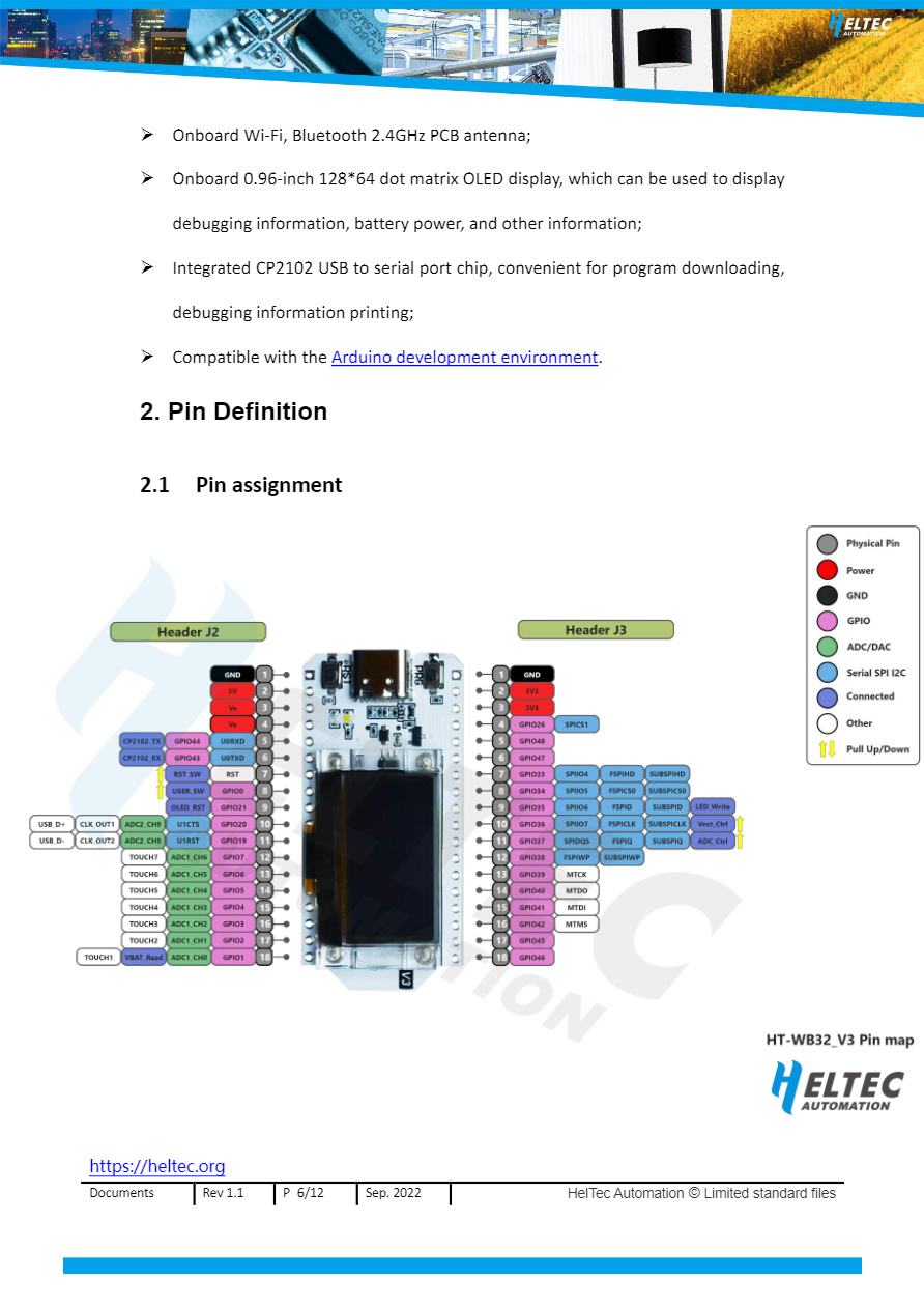
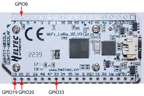
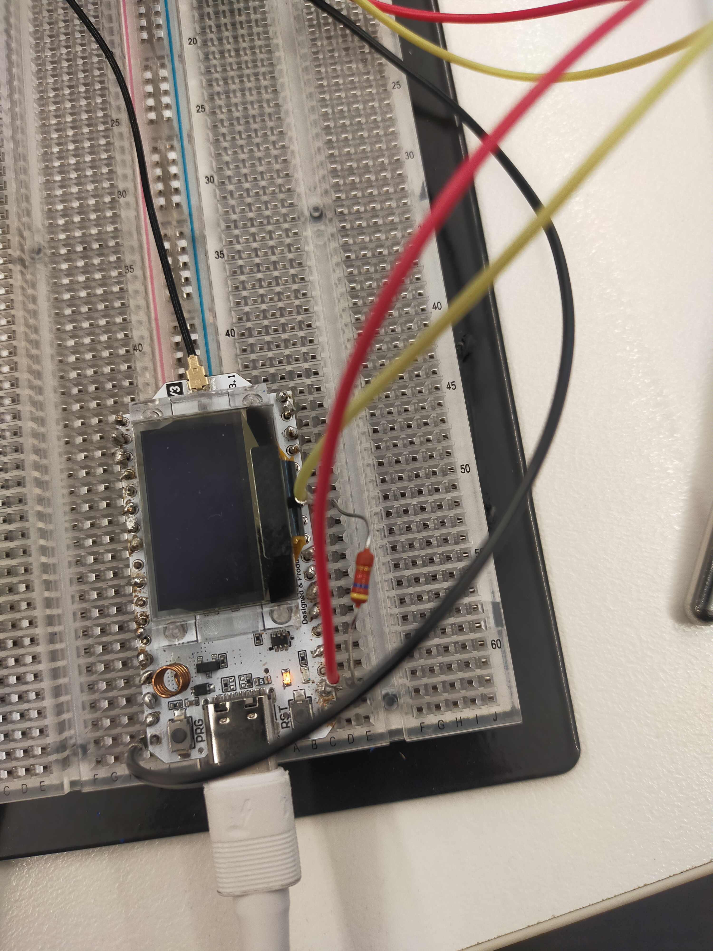
I have attached a DHT22 to my LoRa WiFi OLED (V3) device using pin 46 which the diagram indicates is GPIO. Now I cannot upload programs, it says

Serial port COM4
Connecting......................................

A fatal error occurred: Failed to connect to ESP32-S3: No serial data received.
For troubleshooting steps visit: https://docs.espressif.com/projects/esptool/en/latest/troubleshooting.html
Failed uploading: uploading error: exit status 2

If I disconnect pin 46 it works again. My code is pretty short:

#include "DHT.h"
#include "Arduino.h"
#include "WiFi.h"
#include "LoRaWan_APP.h"
#include <Wire.h>  
#include "HT_SSD1306Wire.h"
//#include "heltec.h"
//DHTesp dht;
SSD1306Wire  factory_display(0x3c, 500000, SDA_OLED, SCL_OLED, GEOMETRY_128_64, RST_OLED); // addr , freq , i2c group , resolution , rst


// DHT digital pin and sensor type
#define DHTPIN 46
#define DHTTYPE DHT22

float currentTemp;
float currentHumidity;
 
void displayReadingsOnOled() {
   
  String temperatureDisplay ="Temperature: " + (String)currentTemp +  "°C";
  String humidityDisplay = "Humidity: " + (String)currentHumidity + "%";
 
  // Clear the OLED screen
  factory_display.clear();
  // Prepare to display temperature
  factory_display.drawString(0, 0, temperatureDisplay);
  // Prepare to display humidity
  factory_display.drawString(0, 12, humidityDisplay);
  // Display the readings
  factory_display.display();
}
// init. DHT
DHT dht(DHTPIN, DHTTYPE); 

void setup()
{
  currentTemp = dht.readTemperature();
  currentHumidity = dht.readHumidity();
 
  pinMode(LED,OUTPUT);
  digitalWrite(LED,HIGH);
 
//  Heltec.begin(true /*DisplayEnable Enable*/, false /*LoRa Enable*/, false /*Serial Enable*/);
  displayReadingsOnOled();
}


void loop()
{
  float temperature = dht.readTemperature();
  float humidity = dht.readHumidity();
 
  if (temperature != currentTemp || humidity != currentHumidity) {
    currentTemp = temperature;
    currentHumidity = humidity;
    displayReadingsOnOled();
  }
    
  delay(2000);
}

Any ideas?

Moved it to pin 48. It now uploads but errors out with rapid rebooting:

Attempting to boot anyway...
entry 0x403c98d8
Guru Meditation Error: Core  1 panic'ed (StoreProhibited). Exception was unhandled.

Core  1 register dump:
PC      : 0x400570e8  PS      : 0x00060830  A0      : 0x82002a00  A1      : 0x3fce2ec0  
A2      : 0x00000000  A3      : 0x00000000  A4      : 0x00000400  A5      : 0x00000000  
A6      : 0x3fce2f2c  A7      : 0x00000040  A8      : 0x82002f9d  A9      : 0x3fce2e90  
A10     : 0x3fce2f2c  A11     : 0x3fce2f2c  A12     : 0x0000000e  A13     : 0x3fce2f3b  
A14     : 0x00000000  A15     : 0xff000000  SAR     : 0x0000001d  EXCCAUSE: 0x0000001d  
EXCVADDR: 0x00000000  LBEG    : 0x400570e8  LEND    : 0x400570f3  LCOUNT  : 0x0000003f  

The ESP32-S3 Datasheet

suggests that GPIO46 is a strapping pin. That may be the problem…

The HelTec V3 pinout diagram shows it is completely available. I moved to another pin (48) which worked

Another example of poor documentation from HelTec

While my DHT22 responds, it responds with 129.90 degrees C and 99.90 % humidity. I contacted Heltec and they said choose another pin without telling me which pin to try. 48 is clearly not used by anything else in the diagram above while almost every other pin has multiple functions. Can I assume that the Heltec V3 has no usable GPIO pins?

That response usually means that the MCU is not seeing the sensor. I use GPIO33 for a DS18B20, so I know that that works (for both input and output). In my present application, I’m also using GPIO6 for analog input and GPIO19 & 20 for an I2C bus.

The multiple functions usually just means that the pin can be used for the identified function or, if the pin is being used for that function, it can’t used for anything else. The trick, of course, is to know which functions are being used by default, if you like, so you can avoid them. Some can also only be used for input, some only for output, and others only under certain circumstances (like the strapping pins).

I’ve not worked through all the pins on the V3 board, but I also initially had trouble trying to use pins GPIO47 & GPIO48—I too figured that, since they had nothing else labelled, they’d be fine. I only worked that one out by working through the ESP32-S3 Datasheet.

But GPIO2…GPIO7 should be fine. The additional labels there just mean that these pins are linked to ADC_1 (if being used for analog signals) or can be used for touch sensitive sensors (I think—I’ve never used them for this purpose). Generally, anything without a purple label should be OK, just checking the datasheet to make sure the GPIO can be used for input/output as required.

Thanks @UniquePete I will try Pins 2 thru 7 tonight as soon as I get home.
I also assume there are no clock frequency issues or changes between the V2 and V3 boards that could be screwing things up?

No clock frequency issues of which I am aware, just the different processor and LoRa chip, which are the sources of pretty much all the problems we are seeing.

Right, am back home and found that the pin number diagram provided by HelTec is completely incorrect. The pinouts in the image above are completely transposed on the board. Now I have no idea which pin is which.

In this image above I am connected to a pin labelled 48 but according to the pinout diagram above it is GPIO5. I changed my code to say Pin 5 and it says NaN for the values. If I choose pin 48 I get 129.9 and 99.90 values

So what on earth should I choose?

That’s the bottom of the board, even though it’s the side with the numbers… So I’d suggest simply connecting your sensor to the pin labelled “5” and using GPIO5 in your sketch. And then cross your fingers…

I am soldered to the 5th pin up from the bottom on that side so according to me the pin labelled 48 is actually GPIO5. I tried this in my code and it just gives NaN. The only time I get values is if I say pin48.
Do I need to set anything to use Pin 5, like using Wire?

OK, just to be perfectly clear, in my current application, I use GPIO6, GPIO19, GPIO20 & GPIO33, and the pins I use are as indicated on the image below:
WiFi%20LoRa%2032%20V3
The pins are labelled correctly, it’s possibly just the presentation of the pin map that is confusing—the pin map shows the top of the board, but the labels are on the bottom. You have to imagine that you are looking through the board to the other side…

The bottom line is that, if you are using GPIO5 in your code, you should be soldering your wire to the pin labelled 5, the pin third from the left at top in my photo, or third from the bottom on the left in your photo.

Working beautifully now.

1 Like