Let out the magic smoke of a component, heltec v3.2, wondering what the component does

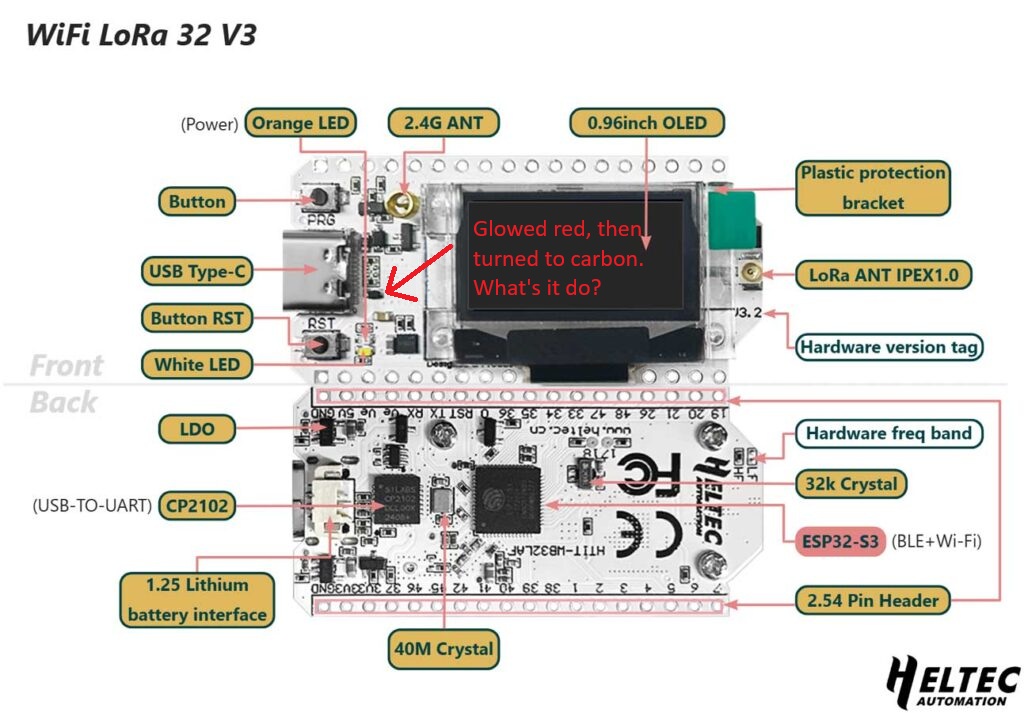
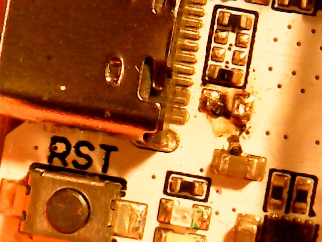
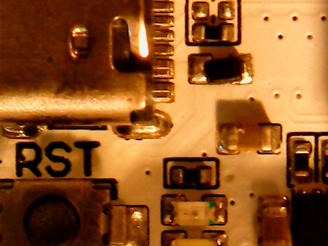
Hey I let the magic smoke out of a component, I had been using it in my vehicle to see how far I could receive a signal from my base station in my local area, all good. Came inside and tried to power it on and it wouldn’t power on via USB through a Samsung USB adapter, tried via a lion battery via the JST connector and it powered on fine, tried the USB again but a different adapter and it burned out a something. Wondering what its used for because I think the Heltec v3 is working via USB and separately via the JST but I’m not keen to using the 2 as I’m guessing it has something to do with power.

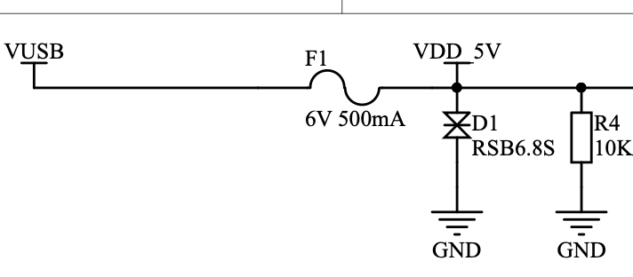
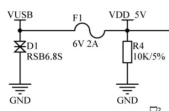
Anyway I’ve pointed it out using this schematic

On my V3 board the component in that location is the ‘resettable’ fuse on the USB power supply circuit. Letting out magic smoke doesn’t sound good but, if it is the fuse, it’s supposed to just reset after overload… So, maybe it was just smoke you saw, and not ‘magic’ smoke… If that’s all it was and it works OK now, it’s probably fine.

1 Like

Concur, any residual flux may have become hot enough to give the appearance of magic smoke.

The top quality magic smoke comes from the chips and they usually end up with a little dimple on them - like a little volcano where the internal pressure gets too much and the smoke just has to escape - and generally just stop working!

1 Like

I dug out my USB scope and manage to snap this photo. Best I could do due to the failing scope.
Not sure how to describe it but like I said it glowed red, let off some smoke and turned to dust, kind of like carbon dust of something burnt. The unit works fine as it was before. Although am yet to use it to charge a battery that attached via the JST connector on the back on the board.
Don’t know what exactly happened between getting out of my car to getting inside but this is the end result.

I’m curious now is this still safe to use? Does this component get used for balancing the Lithium battery via the JST on the rear and USB power?
2025_07_23_09_09_02_779_

This is a snap of a new board that hasn’t been used. For reference:
2025_07_23_09_24_19_57_

Miles better than the normal pictures we get.

That’s the voltage protection (zener) diode, D1, just after the fuse.

You can carry on using the device as normal, but you need to be careful about what you plug in and more importantly, previously plugged in that caused it to be kicked so hard.

1 Like

For what it’s worth, note (from the V3.2 schematic) that the power circuitry on the V3.2 board has changed completely. This includes a change in the location of that diode and the rating on the fuse:
USB%20Input%20Circuit
I don’t think this changes any of the advice given, but it may be part of the reason why we’ve never seen anything like this before. In previous circuits, my guess is that this diode would have been protected from any USB-connected power source over-voltage by the fuse.

1 Like

Oh My Word - that’s the very much censored version.

The product page has a link for the v2 & the v3 schematic. I clicked the link for the v3, naturally, as that’s the device in question.

The link goes to the v2 schematic …

No where on that PDF is a revision number or indeed product name.

Going to find a darkened room to lie down in for an hour.