Keep freezing V3.2 when uploading IDE sketch for two I2C sensors

  • V3 is loaded with Meshtastic firmware
  • Not connected to any other devices, e.g., to iPhone via BLE
  • Put the V3 into boot load before compiling and uploading
  • Relevant Heltec board and library(ies) added to IDE
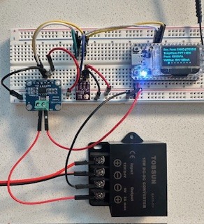
  • GPIO 41 and 42 used for SDA and SCL, respectively
  • Espressif ESP32 library removed
  • Both sensors are supported by Meshtastic firmware
  • Sketch below

Upload is successful but board freezes up. Amber light blinks and/or becomes completely dark. Meshtastic CLI Python tool unable to connect. Have to use esptool to erase and reflash.

One comment on the internet says do not release PRG/Boot button until you see ā€œConnectingā€¦ā€ on Arduino monitor. Necessary?

#include <dummy.h>

#include <Wire.h>

#include <Adafruit_BME280.h>

#include <Adafruit_INA219.h>

#define SDA_PIN 41

#define SCL_PIN 42

Adafruit_BME280 bme;

Adafruit_INA219 ina219;

void setup() {

Serial.begin(115200);

Wire.begin(SDA_PIN, SCL_PIN);

// BME280 Init

if (!bme.begin(0x76)) {

Serial.println("BME280 not found!");

while (1);

}

// INA219 Init

if (!ina219.begin()) {

Serial.println("INA219 not found!");

while (1);

}

Serial.println(ā€œSensors initialized.ā€);

}

void loop() {

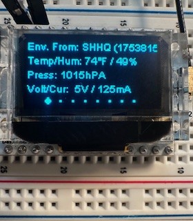
float temp = bme.readTemperature();

float hum = bme.readHumidity();

float pres = bme.readPressure() / 100.0F;

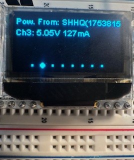
float volt = ina219.getBusVoltage_V();

float curr = ina219.getCurrent_mA();

Serial.printf(ā€œTemp: %.2f C, Humidity: %.2f %%, Pressure: %.2f hPa\nā€, temp, hum, pres);

Serial.printf(ā€œVoltage: %.2f V, Current: %.2f mA\n\nā€, volt, curr);

delay(1000);

}

After getting lost in whether or not I2C sensors with different addresses (INA219 voltage/current 0x40 and BME280 0x76)…and whether or not my V3.2 ESP32-S3 had default non-OLED SDA/SCL pins (mine did…GPIO 41 and 42, respectively), I just wired it up on a breadboard without any programming. It worked.

The only thing I’d recomment is to power all three devices on same voltage; mine works at 5V and didn’t try all three at 3.3V. I mindlessly started with Heltec at 5V and two sensors at 3.3V, and it didn’t work.environ overall%20072925 power

I2C devices have addresses assigned by the manufacturer that mostly don’t clash and often can be physically set to another address - but overall, it’s part of the spec that they have different addresses but with only 128 available, inevitably there is the potential for clashes.

You are unlikely to have a custom / unique LoRa v3 - forum search will reveal many discussion about using the I2C interface that isn’t used by the OLED …

The ESP32 runs on 3.3V but USB is at 5V but from what I can tell from the low res picture you are using some sort of voltage convertor that feeds directly in to the 5V & And pins. You should definitely be mindful of the voltage tolerances of a MCU so you don’t let out the magic smoke. Some I2C devices have a small LDO on to reduce the voltage from 5 to 3.3 and voltage convertor to allow it to work with a 5V powered device and some can work at 5V, like the INA219.

Quite often you can run 3.3V input pins at a higher voltage but for a reduced lifespan …

nmcc, thanks for the reply.

Between the interweb and ChatGPT, there’s seemingly little agreement. I looked at Heltec’s datasheet and only saw SDA SCL related to OLED. If it’s laid out definitively pins 41 and 42 as default non-OLED SDA SCL, I’d appreciate the URL so I can bookmark for next time as I’ll likely forget.

Good advice. The INA219, as you note, is rated for 5V, and I have both 3.3V and 5V BME280’s; I ended up with the latter. Again, thanks for the note.

Hard docs - schematic etc, then forum search, then opinions posted on sites by well meaning individuals who blog their ā€œdiscoveriesā€ and then the total train wreck that is ChatGPT et al.

Here you go: Keep freezing V3.2 when uploading IDE sketch for two I2C sensors and for other ā€˜not definitively using those pins but working just fine’ posts: http://community.heltec.cn/search?q=v3%20I2C%20wire

It’s not laid out definitively, because, like onions Shrek, all this has layers. The ESP32 can usually route any internal peripheral to any GPIO pins. The trick is to choose some pins that are broken out and not connected to any external components before it reaches the header pins.

1 Like