Interrupt Pins on WIFI LoRa 32 (V2.1)(433MHz)

Hi,

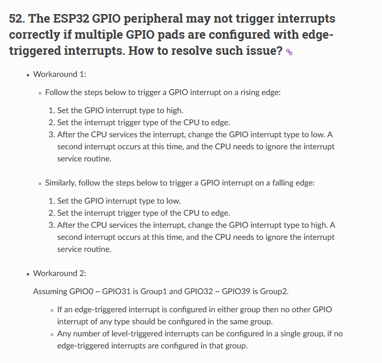
I need to find two Pins on the WIFI LoRa 32 (V2.1) Board, that can be attached to an (or two) ISRs. I have already read a few articles, saying any Pin of the ESP32 can be dedicated as an interrupt Pin, but on the one hand we have some Pins already connected to LoRa, OLED and battery-reading, on the other i have also read, that “The interrupt is handled per port, so groups of pins share a single interrupt handler”.
So maybe it’s not useful to use i.e. 34 and 35, as they are on the same Port(3?), and also may affect readings from Pin37 (battery reading).
I tried it with 22 and 35 for the beginning, then tried 36, 38 and also Pin2, always with ext. PullDownResistor. Most of them, seem to work okay, as long i dont send via LoRa. If i add beginPacket and endPacket to my sketch. The interrupt begins to act weird.
That is why i’d first like to know, which pins you would prefer, for using interrupts with buttons.
Thanks

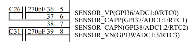
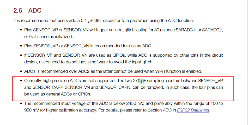
Update2020-12-21: Filtering out the docs, i think GPIO0,2,17,22,23 and GPI36,38,39 come into consideration (21&37 i’ll leave out for battery reading). Just wondering what the capacitors between 36&37 and 38&39 are for…

hi,

I suggest you use the 17 and 22.

"Just wondering what the capacitors between 36&37 and 38&39 are for…"
%E5%9B%BE%E7%89%87

1 Like

Thank you a lot jason! 17 and 22 seem to work fine :slight_smile:

1 Like

Hi, I am also having an issue with the pin 36-39 with the interrupts. I don’t have other options as 17 and 22 are already used and I need 4 push buttons. Now I have enabled interrupts for this buttons, they are pulled down with 10K resistors. The behavior is that 39 is triggered all the time (also triggering 38 at the beginning). 38 is triggering 39 at beginning, and will trigger once correctly when released. 37 is not working, 36 is behaving like 39 but also triggering 39. below is a part of my code. Am I configuring something incorrectly? Please advice, thank you.

#include "driver/gpio.h"
#include "arduino.h"
#define GPIO_INPUT_PIN_SEL ((1ULL<<PUSH_1) | (1ULL<<PUSH_2))
#define ESP_INTR_FLAG_DEFAULT 0
extern "C" {
#include "soc/gpio_struct.h"
}

static void IRAM_ATTR gpio_isr_handler(void* arg)
{
  Serial.print("Triggered by ");
  Serial.println((int)arg);
}
void EnableInterrupts()
{

/*
#define PUSH_1                  39     
#define PUSH_2                  38      
#define PUSH_3                  37     
#define PUSH_4                  36      
*/

  gpio_config_t pGPIOConfig
  {
  GPIO_INPUT_PIN_SEL,
  GPIO_MODE_INPUT,
  GPIO_PULLUP_ENABLE,
  GPIO_PULLDOWN_DISABLE,
  GPIO_INTR_POSEDGE,
  };
  pGPIOConfig.intr_type=GPIO_INTR_POSEDGE;
  gpio_config(&pGPIOConfig);
  gpio_set_intr_type(GPIO_NUM_39, GPIO_INTR_NEGEDGE);
  gpio_set_intr_type(GPIO_NUM_38, GPIO_INTR_NEGEDGE);
  gpio_set_intr_type(GPIO_NUM_37, GPIO_INTR_NEGEDGE);
  gpio_set_intr_type(GPIO_NUM_36, GPIO_INTR_NEGEDGE);
  gpio_evt_queue = xQueueCreate(10, sizeof(uint32_t));

  gpio_install_isr_service(ESP_INTR_FLAG_DEFAULT);
  //hook isr handler for specific gpio pin
  gpio_isr_handler_add(GPIO_NUM_39, gpio_isr_handler, (void*) PUSH_1);
  //hook isr handler for specific gpio pin
  gpio_isr_handler_add(GPIO_NUM_38, gpio_isr_handler, (void*) PUSH_2);
    //hook isr handler for specific gpio pin
  gpio_isr_handler_add(GPIO_NUM_37, gpio_isr_handler, (void*) PUSH_3);
  //hook isr handler for specific gpio pin
  gpio_isr_handler_add(GPIO_NUM_36, gpio_isr_handler, (void*) PUSH_4);
  
}

Hi,this document should help you:
https://docs.espressif.com/projects/espressif-esp-faq/en/latest/software-framework/peripherals.html#the-esp32-gpio-peripheral-may-not-trigger-interrupts-correctly-if-multiple-gpio-pads-are-configured-with-edge-triggered-interrupts-how-to-resolve-such-issue


In addition, in v2.1, gpio37 is used as the battery power detection pin.

1 Like