Goodmorning everyone.
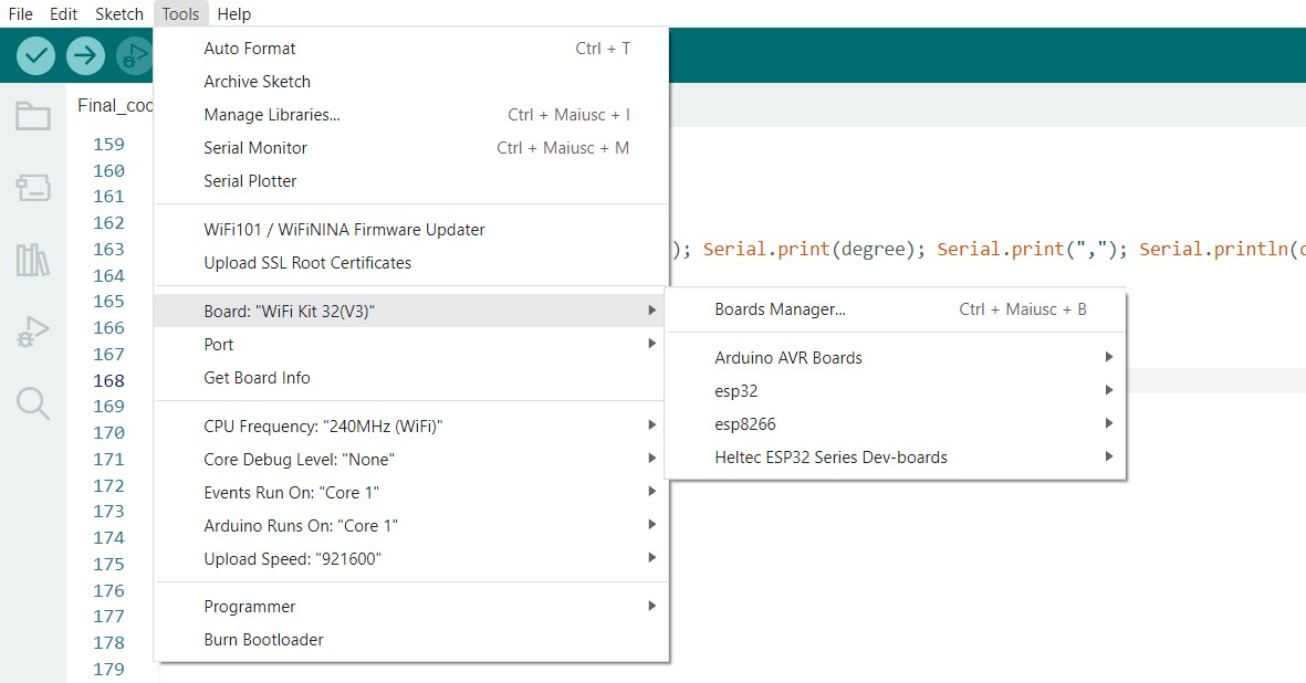
I have a Heltec WiFi kit V3 and I want to connect a mlx90614 and max30101 on it using arduino ide. I found the right driver link for the board and all the example codes work. The sensors have different address and are connected in parallel on the same I2C bus.
However, as I define the I2C pins 48(sda) and 33(scl) I get this error
E (32) gpio: gpio_set_level(226): GPIO output gpio_num error
E (83) gpio: gpio_set_level(226): GPIO output gpio_num error
and the error appears even if I change the pins.
This is my complete code (some parts are commented as I am making several try):
//__________________________________________________________________________________________________________________________________________________________________________
//IMPORTING LIBRARIES
#include <Wire.h> // --> I2C connection
#include "MAX30105.h" // --> Sparkfun library for MAX30101 sensor [https://github.com/sparkfun/SparkFun_MAX3010x_Sensor_Library]
MAX30105 particleSensor; // --> defining particle sensor object used for BPM
#include "Scaler.h" // --> Feature extraction library [https://github.com/eloquentarduino/everywhereml]
#include "Classifier.h" // --> Classification library containing Logistic Regression algorithm [https://github.com/eloquentarduino/micromlgen]
Eloquent::ML::Port::LogisticRegression clf; // --> declare classifier library
#include "heartRate.h" // --> Optical Heart Rate Detection (PBA Algorithm) [https://github.com/sparkfun/SparkFun_MAX3010x_Sensor_Library/blob/master/src/heartRate.h]
#include <DFRobot_MLX90614.h> // --> Melexis temperature sensor library
DFRobot_MLX90614_I2C tempSensor/*(0X5A, &Wire)*/; // --> defining temperature sensor object used for st
//#include <Adafruit_GFX.h> // --> Graphic library for the OLED
//#include <Adafruit_SSD1306.h> // --> drivers library for builtin OLED
//Adafruit_SSD1306 display(128, 64, &Wire1, 21); // --> OLED declaration
#include <Arduino.h>
#include "heltec.h"
//#include <U8x8lib.h>
//U8X8_SSD1306_128X64_NONAME_SW_I2C u8x8(/* clock=*/ 18, /* data=*/ 17, /* reset=*/ 21);
#define BLYNK_TEMPLATE_ID           "TMPL4a5xBd0gm" // --> Blynk dashboard details definition
#define BLYNK_TEMPLATE_NAME         "Smart Watch"
#define BLYNK_AUTH_TOKEN            "MJlb9X9YqOMl8kbWCUxKaJtfbiX-t6n4"
#include <WiFi.h> // WiFi definitions
#include <WiFiClient.h>
#include <BlynkSimpleEsp32.h>
char ssid[] = "smartwatch";
char pass[] = "myhotspot";
BlynkTimer timer;
//____________________________________________________________________________________________________________________________________________________________________________
//DEFINING GLOBAL VARIABLES
//hr
const byte RATE_SIZE = 3; //Averaging
byte rates[RATE_SIZE]; //Array of heart rates
byte rateSpot = 0;
long lastBeat = 0; //Time at which the last beat occurred
int beatsPerMinute; // --> raw BPM
int beatAvg; // --> averaged BPM
//st
byte st_values[RATE_SIZE];
byte st_spot = 0;
int degree; // --> raw peripheral skin temperature in °C
int st; // averaged peripheral skin temperature in °C
//_________________________________________________________________________________________________________________________________________________________________________
void setup() {

  //instrumental initialization
  Serial.begin(9600);
  //Wire.setPins(/*sda*/41, /*scl*/42);
  Wire.begin(48, 33); // object declaration for I2C sensors
  //Wire1.setPins(17, 18);
  //Wire1.begin(); // object declaration for OLED pins

  //hr sensor
  particleSensor.begin(Wire, I2C_SPEED_STANDARD);
  byte ledBrightness = 0x1F;
  byte sampleAverage = 1;
  byte ledMode = 3;
  byte sampleRate = 50;
  int pulseWidth = 411;
  int adcRange = 4096;
  particleSensor.setup(ledBrightness, sampleAverage, ledMode, sampleRate, pulseWidth, adcRange);
  particleSensor.setPulseAmplitudeRed(0); //0 mA
  particleSensor.setPulseAmplitudeIR(0);  // 0 mA
  particleSensor.setPulseAmplitudeGreen(0x19); // 1 mA

  //st sensor
  tempSensor.begin();

  Heltec.begin(true /*DisplayEnable Enable*/, false /*LoRa Disable*/, true /*Serial Enable*/);

  //u8x8.setBusClock(200000);
  //u8x8.begin();
  //display.begin(SSD1306_SWITCHCAPVCC, 0x3C);
  //display.clearDisplay();
  //display.setTextSize(1);
  //display.setTextColor(WHITE);
  //display.setCursor(20, 4);
  //display.print("Initializing...");
  //display.display();
  //delay(2000);
  //display.clearDisplay();

  Blynk.begin(BLYNK_AUTH_TOKEN, ssid, pass);
  timer.setInterval(100L, sendSensor);

  }
//_________________________________________________________________________________________________________________________________________________________________________
// BPM values with MAX30101 sensor
void hrCollection() {
/**
* The particle sensor capture the green led emission from the inner wrist. When a blood pulse happen, the photodiode capture a pulse of light which corresponds to a heart beat.
* In order to be able to capture peaks throw the wrist, the green led has been accurately set up in the setup() section, following the instructions published by the authors
* on page 22 of the paper. [https://pdfserv.maximintegrated.com/en/an/AN6409.pdf]
* The peaks, corresponding to the BPM, are computed throw a PBA algorithm, then, they are averaged with a moving window of size 3.
*/
  long irValue = particleSensor.getGreen();

  if (checkForBeat(irValue) == true)
  {
    //We sensed a beat!

    long delta = millis() - lastBeat;
    lastBeat = millis();

    beatsPerMinute = 60 / (delta / 1000.0);

    // removing signal error
    if (beatsPerMinute < 255 && beatsPerMinute > 20)
    {
      rates[rateSpot++] = (byte)beatsPerMinute; //Store this reading in the array
      rateSpot %= RATE_SIZE; //Wrap variable

      //computing average of 3 samples
      beatAvg = 0;
      for (byte j = 0 ; j < RATE_SIZE ; j++)
        beatAvg += rates[j];
      beatAvg /= RATE_SIZE;
    }
  }

}
//_________________________________________________________________________________________________________________________________________________________________-
// ST values with the particle sensor
void stCollection() {
/**
* Peripheral skin Temperature has been measured in degree Celsius thanks to an InfraRed thermophile that capture the emissivity of the human skin.
*/

  degree = tempSensor.getObjectTempCelsius();

  if (degree > 10 && degree < 50) // removing signal error
  {
    //computing average of 3 samples
    st_values[st_spot++] = (byte)degree;
    st_spot %= RATE_SIZE;
    st = 0;
    for (byte z = 0 ; z < RATE_SIZE ; z++)
      st += st_values[z];
    st /= RATE_SIZE;

  }

}
//_____________________________________________________________________________________________________________________________________________________________________________
void sendSensor()
{

  Blynk.virtualWrite(V0, particleSensor.getGreen()); // send raw Blood Volume Pulse to dashboard
  Blynk.virtualWrite(V1, tempSensor.getObjectTempCelsius()); // send raw temp to dashboard

}
//_____________________________________________________________________________________________________________________________________________________________________________
void loop() {

  hrCollection();
  stCollection();

  int features[] = {beatAvg, st};

  if (!processor.transform(features))
  return;

  // Display raw values
  Serial.print(beatsPerMinute); Serial.print(","); Serial.print(degree); Serial.print(","); Serial.println(clf.predictLabel(processor.X));

  Heltec.display->clear();
  Heltec.display->setTextAlignment(TEXT_ALIGN_LEFT);
  Heltec.display->setFont(ArialMT_Plain_10);
  Heltec.display->drawString(0, 0, "Hello world");
  Heltec.display->display();
  //u8x8.setFont(u8x8_font_chroma48medium8_r);
  //u8x8.setCursor(0, 1);
  //u8x8.print(beatAvg);
  //u8x8.display();

  Blynk.run();
  timer.run();

}