HTCC-AMO2 programming and debugging circuit

I have purchased HTCC-AMO2 and designed and built a circuit board for a custom design.
I am wondering how to program and debug this device from the Arduino IDE.

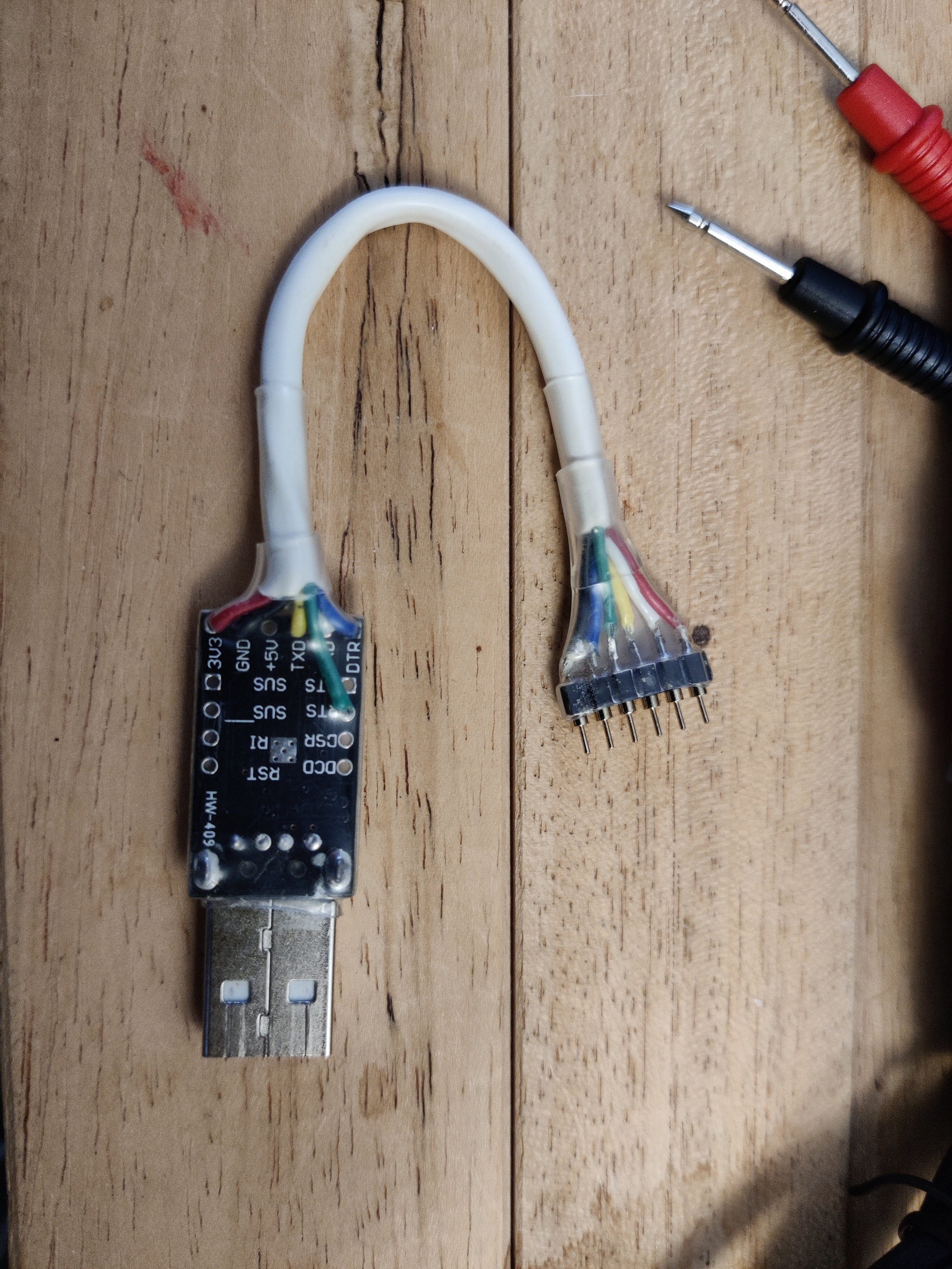
I have wired RX1 and TX1 to support a USB to serial connection such as USB to TTL Serial 3.3V UART Converter Cable with FTDI Chip Terminated by 6 Way Header (you can search that on Amazon and see what I mean).

Will this just work? Should I have designed in the reset pin somewhere? I am hoping somebody can direct me or explain what is needed to program and debug this standalone device.

Hi,

indeed RESET and USR1 (GPIO16) pins are required to enter bootmode and program the AM02 module.

You will find relevant schematics design here:

There is a convenient “autoboot” section that can be used to implement automatic RESET/USR1 procedure using RTS and DTR pins on the FTDI converter.
You can otherwise do it manually by including buttons for both RESET and USR1.

1 Like

As @piecol said you can use the referenced autoboot design. However, most FTDI USB Adapters only expose DTR and CTS pins along RX/TX, 3V3 and GND. Only a few additionally expose the required RTS pin. And if they do, they usually don’t do so on the 6 Way Header but instead on some pad on the PCB you can solder on. This makes using these Adapters for quickly connecting a custom board hard to use.

I wonder if there is a way to change the requirement from RTS to CTS in some way. I believe this is hard coded into the CubeCellelftool.

Yes, the pin order on serial bridges is not in favour of the RTS/DTR thing. But you can easily solder some wires to a 6pin header and you have your custom serial programmer at hand. Some heatshrinking tube would make it sturdier.

1 Like

I got this from AlexFR. I use a HiLetgo 2pcs CP2102 MICRO USB to UART TTL Module 6 Pin Serial Converter STC Replace FT232 to connect to this.

https://oshwlab.com/philscheiman/testhtccm02