Greeting from heltec.
They are no different in terms of battery. you can refer this:https://resource.heltec.cn/download/
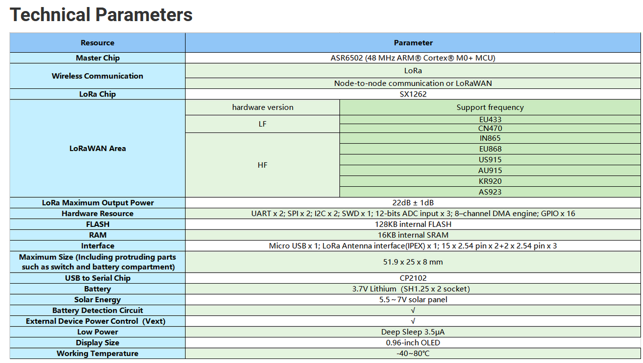
ab02:

Greeting from heltec.
They are no different in terms of battery. you can refer this:https://resource.heltec.cn/download/
ab02:
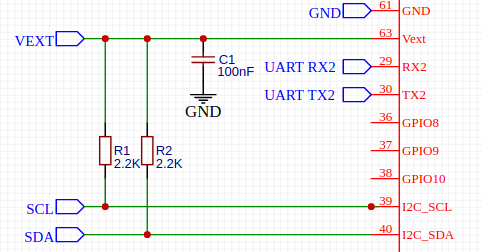
@jasonXu So i want to double check with you. So in my project I have to use I2C numebr 2 becouse I2C number 1 is busy tiwh oled?
The pin number of I2C numer 2 is 36 and 37 ?
yes, The pin number of I2C numer 2 is 36 and 37.
Actually IIC No. 1 can be used. Use IIC device slave address to select device. OLED’s device slave address is 0x3c.
Got it.
In ab01 I use 2k2 resistor in sda and scl. Your recomned to use in ab02 ?
yes, our recomned to use in ab02
Hello Friend, out of topic question:
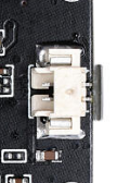
It is possible connect the LiPo battery over a pin instead SH1.25-2.
The connector at the bottom of the board difficult connect or disconnect battery after the board are solder to PCB.
Hello friend, can you explain more please I don’t understand
hi,
It is possible connect the LiPo battery over a pin instead SH1.25-2.
You think this is not easy to use. You can change this to the form of pin headers (on the pcb)
Do you mean that I should unsolder the connector on the board and change it for a header pin?
Not available on existing pins?
hi,
sorry, I didn’t make it clear. I mean that when you design a new PCB, you need change the package of the battery compartment to that of the pins package.
Sorry about this, but i dont understant what you want to exaplain me.
The is other way to connect the battery or battery only can be connected over this port?:
hi,
sorry, I thought you wanted AM01.
If it is AB01, there should be no other way.
Ok friend, got that. Thanks.
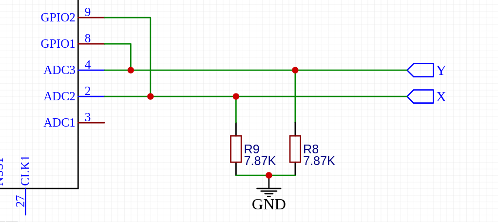
@jasonXu Hello friend. I need to read analog voltage to get resistor value with know resistor voltage divisor. Also I need to measurement the current output voltage from GPIO pin.
The problem is the hardware only accept 2.4 v on ADC. I make a voltage divisor to get down the voltage but affect my other voltage divisor.
There is a workaround to read 3.3 volts with ADC or any idea how solve my problem ?
This is my circuit but I cant work like this because the ADC cant read 3.3 volts (the GPIO voltage)
Hi @dserrano
The voltage divider circuit should be a network of pull-up resistors and pull-down resistors. For example, just like this:
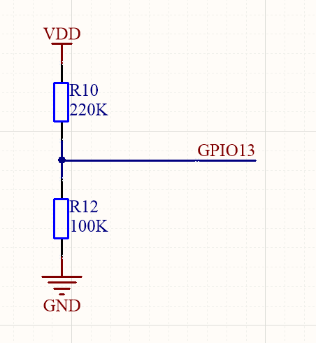
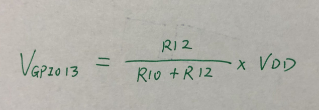
In the example, the voltage on GPIO13 should be calculation like this:
Hi, did you made a SDS011 sensor integration?