Htcc-ab01-v2 color problem

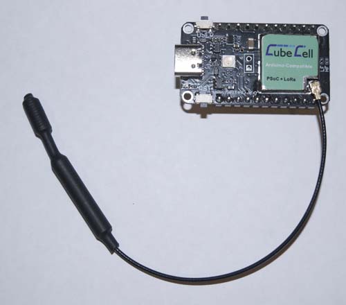
I use an htcc-ab01-v2 (With the previous version, htcc-ab01, the problem was not there).
When I send the RED color, sometimes (1 time in 4 attempts or once in 5 approximately), i get the ORANGE color.
I have similar problems with other colors too.
Can you help me solve the problem?

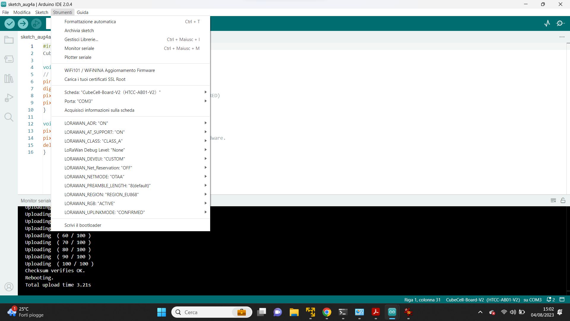
You can reproduce the error using the RGB example (modified on the 2 lines in bold).

#include “CubeCell_NeoPixel.h”
CubeCell_NeoPixel pixels(1, RGB, NEO_GRB + NEO_KHZ800);
void setup() {
// put your setup code here, to run once:
pinMode(Vext,OUTPUT);
digitalWrite(Vext,LOW); //SET POWER
pixels.begin(); // INITIALIZE NeoPixel strip object (REQUIRED)
pixels.clear(); // Set all pixel colors to ‘off’
}
uint8_t i=255;
void loop() {
// put your main code here, to run repeatedly:
pixels.setPixelColor(0, pixels.Color(i, 0, 0));
pixels.show(); // Send the updated pixel colors to the hardware.
delay(200); // Pause before next pass through loop
pixels.setPixelColor(0, pixels.Color(0, i, 0));
pixels.show(); // Send the updated pixel colors to the hardware.
delay(200); // Pause before next pass through loop
pixels.setPixelColor(0, pixels.Color(0, 0, i));
pixels.show(); // Send the updated pixel colors to the hardware.
delay(200); // Pause before next pass through loop
//i+=10;
}

Many thanks.
Marco

Add pixels.setPixelColor(0, pixels. Color(0, 0, 0)),After the lights are on

Thank you for your answer.

I try whit the simplest sketch:

BUT EVEN IN THIS CASE THE LED ALTERNATE RANDOMLY BETWEEN RED AND ORANGE.

#include “CubeCell_NeoPixel.h”
CubeCell_NeoPixel pixels(1, RGB, NEO_GRB + NEO_KHZ800);

void setup() {
// put your setup code here, to run once:
pinMode(Vext,OUTPUT);
digitalWrite(Vext,LOW); //SET POWER
pixels.begin(); // INITIALIZE NeoPixel strip object (REQUIRED)
pixels.clear(); // Set all pixel colors to ‘off’
}

void loop() {
pixels.setPixelColor(0, pixels.Color(255, 0, 0));
pixels.show(); // Send the updated pixel colors to the hardware.
delay(500); // Pause before next pass through loop
}

Some ideas to solve this problem?

For what it’s worth, I just loaded your sketch onto a CubeCell V2 (powered either via USB or battery, with nothing else connected) and the NeoPixel just sits there solid red—no orange at all.

You may have a dud NeoPixel or board.

Thanks for the reply.

This thing is frustrating.

I tried with at least 4 different HTCC-AB01-V2, and the result is always the same:
the colors are often wrong.

In the attached image, the LED is orange, and shortly after, it changes to red, and then orange again and so on, randomly.

And this is the ide configuration:

If you have any idea let me know, please

Well, maybe my particular test was less relevant than we may have thought. Here is a picture of MY CubeCell V2 Dev-Board:

DSC_7039

Note the ‘old’ label (not the laser etched version), no V2 identifier and it came with the smaller spring antenna, not that that makes any different in the present case. But it does have the USB-C connector and is the same as the image on the HTCC-AB01_V2 Datasheet and Pin Map, and it does have the ASR6502 processor.

Heltec has some form here though, quietly introducing upgrades to boards without necessarily noting anywhere anything that might have changed. I note that there is nothing at all about the V2 boards in the Cubecell hardware update log.

So it may be that you have an ‘updated’ V2 board that includes some change that has impacted the operation of the NeoPixel. Actually, I can’t quite make it out, but is that a V2.2 there under the IPEX connector on your board? If so, then, quite apart from the present problem, it would be really good if Heltec would post some information in relation to what has changed on the board since the initial V2 release.

I can confirm that with the previus version with the printed label (not lasered), it worked perfectly.

It is ONLY with the new (V2.2) lasered version that there are problems.

HELTEC, CAN YOU HELP US, PLEASE??

1 Like

I have 4 of these V2.2 Cubecells and the code above shows solid red on 2 of them that I have tested.
My issue is that the ADC ports don’t seem to work and apparently there are 3 of them (from scouring the internet) but I can’t find the documentation to show that.

There are indeed 3 ADCs on the 6502, but the CubeCell Dev-Board [V2] only breaks out two of them, and only one of those is generally available—the other is dedicated to reading the battery voltage. See


The pinout diagram suggests that the single ADC pin on the dev-board is used in conjunction with the reading of the battery voltage, but I do not believe that this is the case.

Rather than hijacking a thread, possibly best to stick to the new topic you created so all the answers can be focused there?

Yes, it would probably be more appropriate to continue any discussion on the CubeCell ADC under the [Analog Read CubeCell] thread (for example)…

Thanks for your help.
What pin on the actual board board is connected to the 3 ADCs?

I didn’t realise I had made a serious infringement of the rules. Perhaps in future you could be helpful rather than castigate a new member.
You get complaints about “hijacking” an existing relative thread and complaints about starting a new one.

Not sure if there are any rules but thread hijack I think is punishable hard labour on the Arduino forum :wink:

I had no intent of castigating you, maybe it’s a language / cultural thing - just a suggestion from experience from seeing split threads ending up all over the place with answers!

Well you will be happy to know that I found the answer on xhamster.com