HTCC AB01 Soil Moisture analog read pin ADC

Hi everyone. I try to read an analog soil moisture sensor (soilwatch 10), I use the ADC pin to read the values, but the reading doesn´t change. Do you know why does this happen?
I read here: HELTEC DOCS " ADC input pin had been used for battery voltage reading default." “In order to read other analog signal, user need remove the resistance BR1, then the ADC header will be free”

Is that correct? I think it’s impractical for any purpose of reading analog sensors. Or maybe I don’t understand what they’re saying.

Here a basic code example I used
void setup() {
Serial.begin(115200);
pinMode(ADC, INPUT);
}
void loop() {
int voltage= analogRead(ADC);
Serial.print("ADC = " );
Serial.println(voltage);
delay(1500);
}

Are you using the original CubeCell Dev-Board, or the V2 model? The original board is based on the ASR6501 processor, and only has a single ADC. The V2 board uses the ASR6502, which has three ADCs, although it appears that only two are used—one now dedicated to the task of reading battery voltage and the other available for general use.

The schematic for both boards shows a solder bridge on the [battery] ADC circuit (although I can’t see it on the V2 board) and I have seen comments to the effect that this has to be removed to use the ADC for anything other than measuring the battery voltage. Looking at the board schematic:


the ADC is pulled to Ground, through the solder bridge, so that will have an impact on any use of the ADC while the solder bridge is in place.

The battery will only be connected, through a MOSFET switch, for the purpose of measuring its voltage, when VBAT_ADC_CTL is LOW. This is managed automatically when using the getBatteryVoltage() function to retrieve the battery voltage, but if set HIGH, the battery should not be in the circuit. I don’t know how that might help in your case, but I doubt that having the ADC pulled to Ground will be helpful.

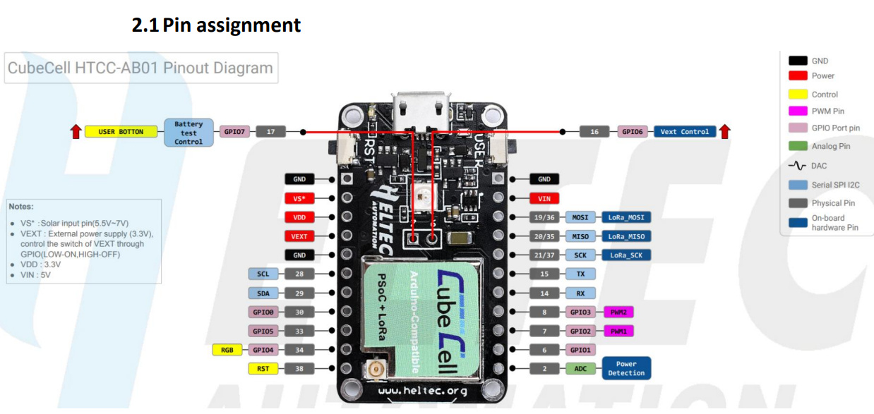
Just for the record, while the schematic suggests that VBAT_ADC_CTL is GPIO7, my experimentation (Serial.println(VBAT_ADC_CTL)) suggests that it is actually GPIO27.

EDIT: I would seem that the GPIO labels on the CubeCell more generally do not map to the underlying ‘number’ so, as already noted, GPIO7 maps to 27, GPIO6 to 26, GPIO0 to 2, GPIO1 to 49, and on it goes, in no logical order that I can divine. The upshot of all that is that, if you want to address GPIOn, you’d better user the GPIOn identifier, not just the number “n”.

And yes, I agree that none of this is very practical for anything other reading the battery voltage.

However, if you are purchasing a CubeCell Dev-Board today, I think you would be supplied with the V2 model and in that case, the ADC pin should be free for any appropriate use.

Hi, UniquePete! Thanks for your response.

I’ve already purchased the AB01 based on ASR605x (ASR6501, ASR6502). Those chips already integrate the PSoC 4000 series MCU and SX1262. Here is the link

As you can see, the image shows one ADC pin in this diagram. About the ADC pin, the document explains:

"ADC1_CH0 is used to read the lithium battery voltage, the voltage of the lithium battery is: VBAT = 100 / (100+390) "

Hi @galad,

The link in your post appears to be to a V2 Dev-Board (ASR6502), while the pinout diagram is for the V1 Dev-Board (ASR6501). The pin descriptions are supposed to be the same, but the operation of the ADC pin is different.

Does your Dev-Board have a micro-USB port (V1) or a USB-C port (V2)?

Unfortunately, there are also several aspects of the document to which you refer that are not correct. The statement:

"ADC1_CH0 is used to read the lithium battery voltage, the voltage of the lithium battery is: VBAT = 100 / (100+390) "

I believe actually refers to the ESP32 processor in the WiFi LoRa 32 dev-board. (Look at p.13 of that document and you will see references to ESP processors, which have nothing to do with the CubeCell boards). I believe that this was just sloppy document preparation on the part of Heltec. Fortunately, these errors have not been carried over to the documentation for the V2 board.

According to the schematic diagram for the CubeCell Dev-Board (V1), the voltage divider used on that board for battery measurement is 10kΩ/10kΩ, but the associated calculations are all managed inside the getBatteryVoltage() function in any case.

But the first issue to resolve is what version of the CubeCell Dev-Board you are using: V1, which looks like the pinout diagram that you’ve posted, or V2, which looks almost the same but has a UCB-C connector and LF/HF resistor options, on the opposite end of the board, that are not present on the V1 board. The labels on the processor module of both versions are exactly the same on the V1 & V2 Dev-Boards that I have—the label on the V2 board does not look like the one in the Heltec advertisement (which looks like a pre-release photo that has simply not been updated, like that for the Wireless Stick Lite V3 board).