
Dear All,
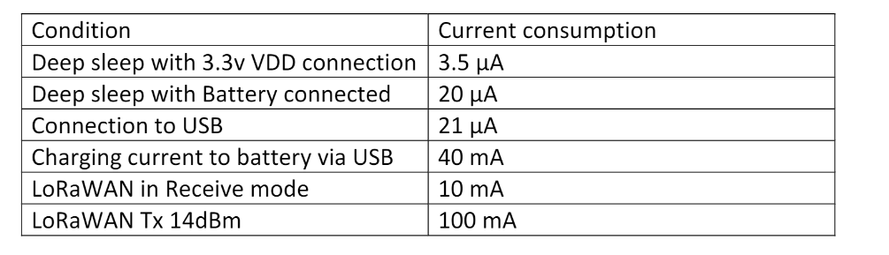
I have an HTCC-AB01 connected to some sensor, I am using a battery 3.7 Volt and 5000mAh as a power supply in the Vin pin, and the power supply for the rest of the circuit come from the Vext pin. I put the HTCC-AB01 in deep sleep and it wake up every 15 minutes(and from Vext I measure 0V) or if external interrupt occurs. The voltage measured by a multimeter at day 0 was 3.81, now after 6 days the level it is 3.68V. When it is in deep-sleep if I measure the current with the multimeter it is 0, but maybe it is due to the multimeter resolution (in the datasheet the current in the deep-sleep it is 3.5uA).But if the battery continues to follow this decay, in a maximum of one month I think it is discharged. There is a way to decrese the power consumpution? Can I use a capacitor in parallel to the battery? Or I need to connect a super-capacitor between Vext and Gnd?
Someone have an idea?
Best
Giovanni
HTCC-AB01 Battery Power Supply and Capacitor
Make sure you turnoff VExt before you go to sleep…
void vextOFF(void) // Vext OFF
{
  pinMode(Vext, OUTPUT);
  digitalWrite(Vext, HIGH);
}
and to turn it on when you wake up:
    void vextON(void)
    {
      pinMode(Vext, OUTPUT);
      digitalWrite(Vext, LOW);
      delay(500); // to allow the powerline to settle maybe should go up to 1s
    }
Hope this helps.
Also make sure you use resistor with your interrupted pins as those consume a lots of power when shortened.
last but not least, invest in Power Profiler Kit II it will be a life saver when it comes to learning about the power consumption.
Cheers,
Jay
Avoid serial communication.
See my German blog post
Cheers, Claus
Thank you,
I have still one doubt,
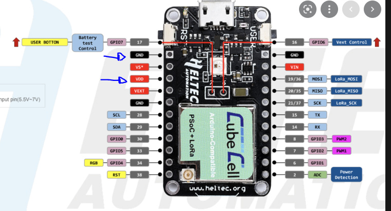
regarding the attached image. I have an external battery 3.7 Volt 5000mAh, the best pin where I need to connect the battery are of course GND and VDD pin like in the following image?
. Because now in my case the battery it is connected to the Vin pin and sending a message every 15 minutes the voltage of the battery in 2 weeks came from 3.81V to 3.59 I think in max one month the battery will be flat.
Best
Giovanni
I had similar issues with my setup. If you look at the schematic, you see that VIN is basically the same as the USB +5V line. It is connected to GND via a 10 kΩ resistor, and the charging circuit including the small orange LED is powered from this line. Furthermore, it is specified for a voltage range of 4.2–7V.
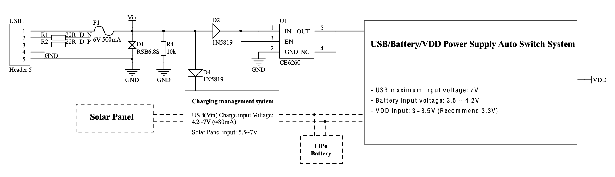
I connect my (non-rechargeable) LiSOCl₂ battery via a Schottky diode to the LiPo battery connector of the board. Unfortunately, the only connection available for this is the small socket on the bottom side of the board, there is no pin.
Powered this way the module uses about 10 µA in deep sleep, although this varies significantly between samples of the board as I had to find out. The diode prevents the battery from being charged when a USB connection is active.
VDD would work, too, but only if you provide for an external 3.3V regulation as the 3.7V voltage from the battery is too high.
Hello!
I have this board, why it does not work from battery, if I connect it with provided cable to that small battery connector? Thanks!
On what basis have you concluded that it does not work?
Hello!
Nothing happens on TTN, no led blinks if I press reset button (compared when it is plugged to USB)
I use this code:
*pardon, false flag! after 1h test I finally got message to TTN… seems duty cycle code part made limits that right after reboot/or taking out battery it dos not transmit. Thanks for support! patience is the answer 