
Hi, I have two Heltec WSL_V3 devices in 868MHz. Both devices work, and I had meshtastic installed. On the first one I was able to change the firmware by flashing it from USB and Chrome, without any problem. The second one, when I connect it to any computer via USB, the message “Device not recognized” appears. The device turns on with the USB power supply and works normally, but I can’t update the firmware. I tried all the USB ports, I updated the drivers, and tried on another PC. The first device is correctly detected, the second one is not. Assuming that the chip on the Heltec that manages the communication with the USB is damaged, is it possible to reprogram the Heltec via the RX and TX pins, and an external USB UART adapter?
heltec wsl_v3 not recognized from any usb
Yes, but you will most likely have to remove the CP1202 serial to USB chip or cut the Tx/Rx lines to splice in your own adapter.
A well lit hi-resolution picture of the back of the board should allow us to identify those lines.
many thanks for the answer.
I was hoping it was simpler, a bit like you do with an ESP8266-01… Is there any other way to upload another firmware on a Heltec WSL_V3 where recognition via USB fails?
Nope
If you look at the schematic you’ll see that the USB lines aren’t broken out, it’s just the U0Rx/Tx via the CP2102 chip.
@nmcc as far as I can see on the schematic, the CP2102 is between the Tx/Rx and the USB connector. Wouldn’t that mean that you could hook up your own Serial chip to the Tx/Rx lines?
Yes, that was what I was saying in my first reply - remove the potentially broken chip or cut the lines and then tap in to them - but I don’t have one so I can’t say where to cut …
You can try and solder on the USB pins if you have a very fine tipped iron & a steady hand.
The Tx/Rx lines are simply broken out to the headers so if the defect isn’t on the pin side, it might just work leaving the board intact.
1 Like

The schematic with the chip numbers + GPIO number + U0Tx/Rx labels on the chip 
The CP2102 with the U0Tx/Rx labels
The header pins with the GPIO number 

The picture of the bottom of the PCB with the lines marked 
So, now I look harder, yeah, attach the USB UART. to the header pins - I’d try to power via the 5V pin rather than have the CP2102 active, but it may well work with the USB plugged in.
Don’t forget to cross the wires Tx to Rx and Rx to Tx!
1 Like
many thanks again for the support guys.
then, this morning I’ve connected my USB serial adapter (in 3.3V) to the RX and TX pin, powering the module with the 3.3V out from the adapter: Look at the photo:
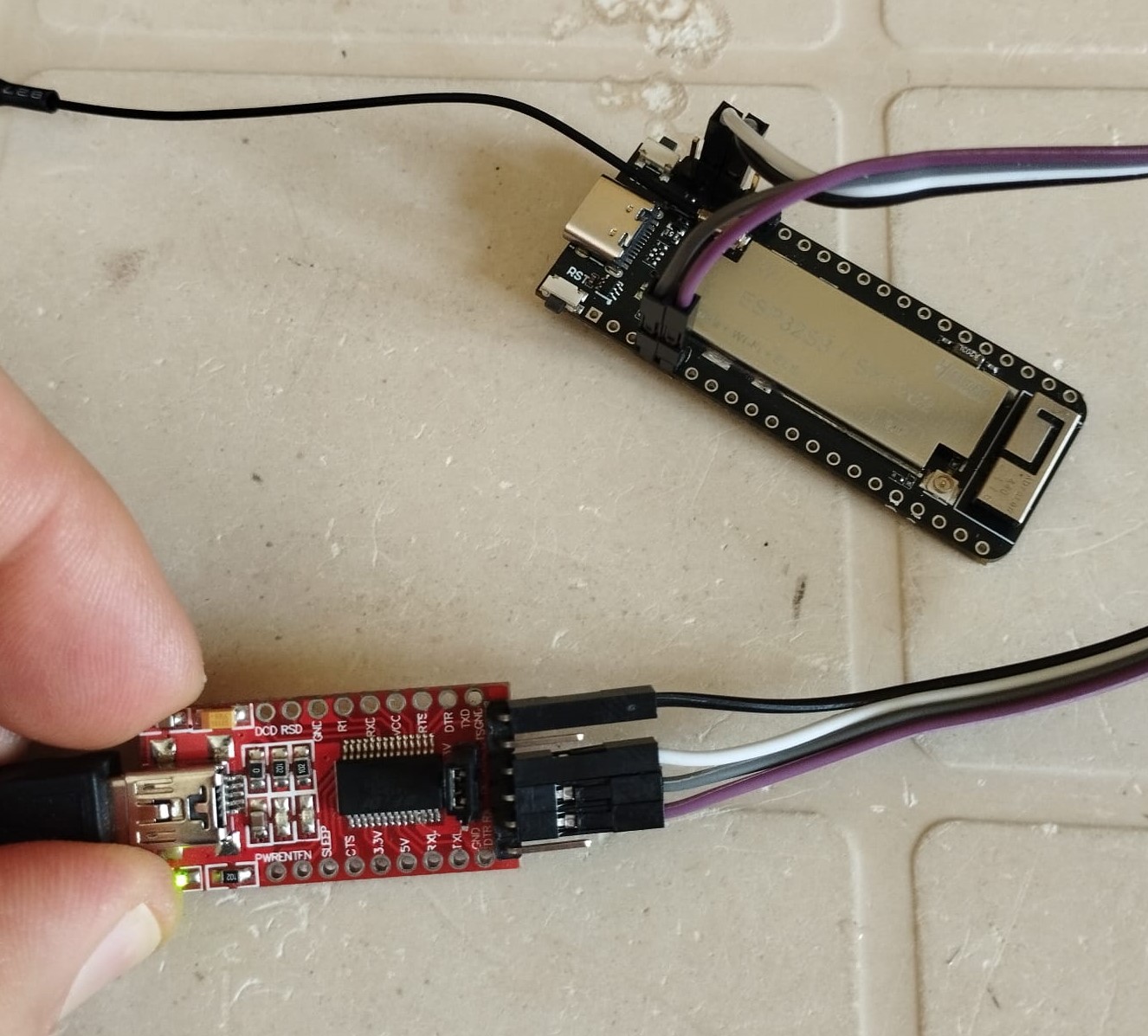
When I power the usb serial adpater, the Heltec turns on as well as if is powered from its USB C port.
Following the instructions on meshtastic website, regarding connection by CLI (here) I’ve tried to connect to the heltec with the command esptool chip_id, to veryfy the connection.
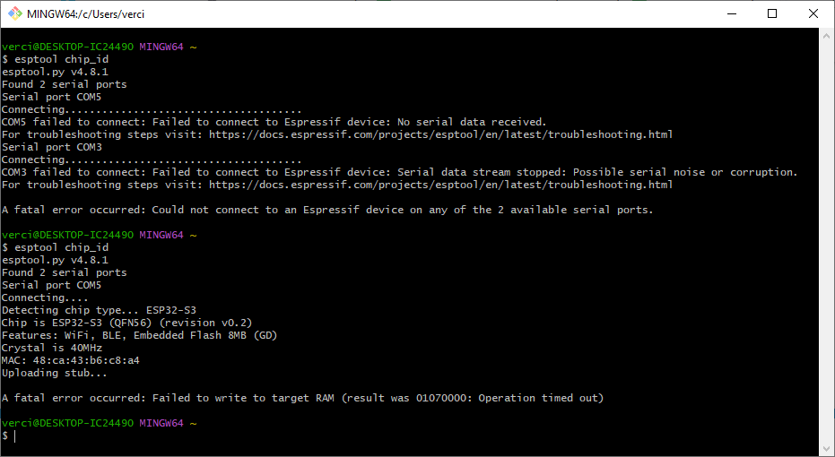
Below the outputs of the command with the device in “normal mode”, and in “flashing mode” (pressing and holding the BOOT / USR button while plugging in the USB cable)
In “flashing mode” I can read some info from the board, but with an error:
$ esptool chip_id
esptool.py v4.8.1
Found 2 serial ports
Serial port COM5
Connecting....
Detecting chip type... ESP32-S3
Chip is ESP32-S3 (QFN56) (revision v0.2)
Features: WiFi, BLE, Embedded Flash 8MB (GD)
Crystal is 40MHz
MAC: 48:ca:43:b6:c8:a4
Uploading stub...
A fatal error occurred: Failed to write to target RAM (result was 01070000: Operation timed out)
Powering the heltec with 5V, by PIN 1, switching accordingly the voltage on the USB UART, the board turns on but I can’t retrive any information with the command esptool chip_id, both in “normal mode” than in “flashing mode”.
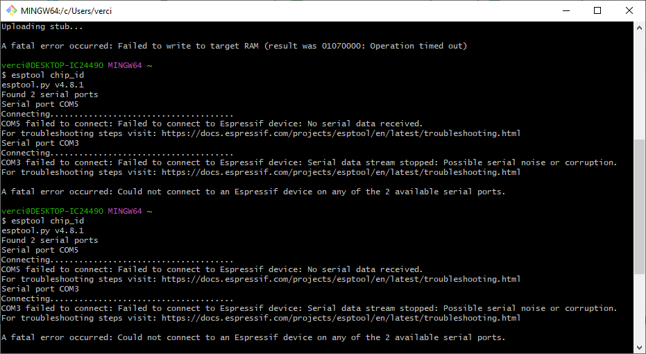
I have the feeling that the problem is not the CP2102, but that the power is not reaching something properly. Why with 5V the module turns ON and works normally, but doesn’t respond?
It’s a bit simpler than that but is very sequence dependent. Press and hold BOTH buttons. Let go of BOOT first, so it is reset / boots and detects the Usr / Flash pin is active. It’s not reliant of providing power by any means, USB or otherwise, it’s available 24/7/365 …
The FT232R adapter has a very low power provision - 50mA if I recall - so not the best way to give the board power at 3.3V - there is the possibility that it’s just not quite enough to get the ESP32 booted properly, hence the error message regarding the RAM.
Powering at 5V will power up the CP2102 USB-Serial chip which may have some bearing on the situation - it may be jamming the Tx/Rx lines in some way.
The next thing to try is to get some beefier 3V3 supply to the board - as odd as it may be, you can use your other board’s 3.3V output as long as that donor board isn’t doing anything - ie it’s been flashed with an empty sketch.
Overall it may be simpler to return this board as dead on arrival.
PS, Screen shots suck, dark mode screen shots suck more, my optometrist says I shouldn’t try to look as my ageing eyeballs are already shot - if you can copy & paste in future that would be preferable as it’s readable by most if not all and can be copied & pasted for technical info.
I also think that dark backgrounds are bad, but I can’t choose. I have however reported the screenshot output in text format, trying to format it properly, but evidently it was not enough.
I will try with a more powerful 3.3V power supply. Thanks
I’m here, again.
I’ve tried powering the heltec with an external source at 3.3V, connecting the FT232R at the TX and RX pin on the module
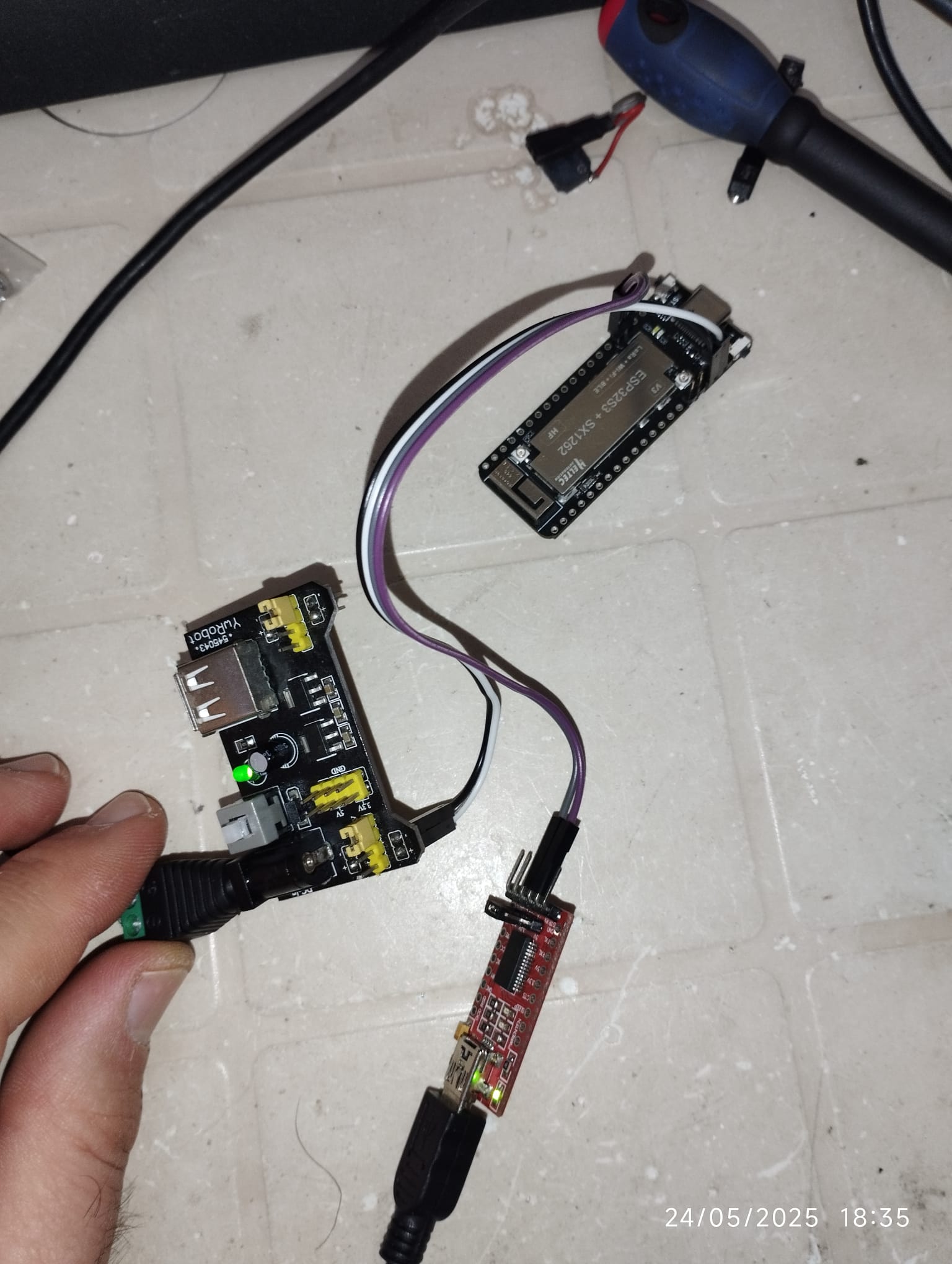
@nmcc you were right, this time I didn’t get the RAM error that appeared previously.
I then tried to upload the Meshcore firmware via the web flasher, since the Meshtastic was currently installed.
The installation procedure ended without errors, as you can see below (sorry for dark background)
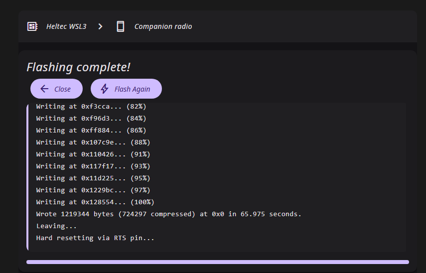
But, when I turned it on, the Meshtastic firmware was still there. It’s hard to die, the device now belongs to him 
At this point I give up, and I keep it with Meshtastic.
Thanks again for the help, it was very informative anyway.
You took a screen shot - just highlight the text and copy & paste.
Um, that would have flashed the device with some other type of mesh radio firmware that may well look like Meshtastic. This was your choice to flash this code. Was this what you wanted?
Now that you can flash your device, what do you actually want it to do?
No it was’t. The module already had the Meshtastic firmware. I wanted to replace it with Meshcore to make a comparison between the two communication systems. Even though the Meshcore installation procedure seemed to have completed successfully, when I rebooted the module, Meshtastic was still there, so the installation failed, and I didn’t get what I wanted.
None of us knew that you wanted to compare with Meshcore so it seemed like you’d flashed that and couldn’t tell if it was Meshtastic or Meshcore because, well, detailed text only serial logs of output? As far as we knew you just wanted to be able to flash the board, so we helped with that.
It does seem very odd that the result on the website says it succeeded but didn’t. Maybe try your esptool command line setup?