
Yes, you are correct !!!
Heltec Wifi LoRa V2 battery management
@Supporter thanks!
This weekend I’ve managed to use a li-ion battery and it worked fine. Thanks for your help!
Now I’m heading to a circuit to measure battery voltage (without wasting a lot of power power, what happens when using a simple voltage divider). Per my understanding, there is no “out-of-the-box” way to do this in this module (nothing inplemented yet). Am I correct? I ask you that because if there’s something like this lready inplemented on the module, it will save me some time.
Best regards,
Pedro Bertoleti
If you use V2 board, it’s have a battery voltage detect circuit. Also you can refer to here:
@Supporter, per my understanding, the forum topic you said suggest a voltage divider using gpio 13 (an ADC channel). It doesn’t have mention to an already implemented circuit on v2 board, right?
That is just my advice. You can see this part on the schematic diagram we provide:
Oh, now I see it! Have you referred to “LiPo electtricity & Vext” part of the schematic, right?
Per my understanding, when GPIO 21 is set to ‘0’ (low logic level), GPIO 13 (ADC 2:4) reads battery voltage. Is this correct?
Also, assuming what I said above is right, when Q3 has no conduction between source and drain (when GPIO 21 is ‘1’ or configured as an input), Vbat (what can be any value from 0 to 4.7V) will be directly wired to GPIO 13 (ADC 2:4). Is this a real risk of burning / destroy ADC2 (as it can support, at its maximum, 3.3V only)?
-
when GPIO 21 is set to ‘0’ (low logic level), GPIO 13 (ADC 2:4) reads battery voltage. Is this correct?
-Yes -
Is this a real risk of burning / destroy ADC2 (as it can support, at its maximum, 3.3V only)?
-Yeah, at this time, you need config the GPIO13 as a normal GPIO.
So, to sum up:
A- When GPIO 21 is set to ‘1’: adc2:4 (gpio 13) will read full vbat value (probaly something greater than 3.3V).
B-When GPIO is set to ‘0’: adc2:4 (gpio 13) will read vbat in voltage divider (certainly lower than 3.3V).
For “A” case, GPIO 13 must be configured as input? Is it tolerant to 4.7V working as input?
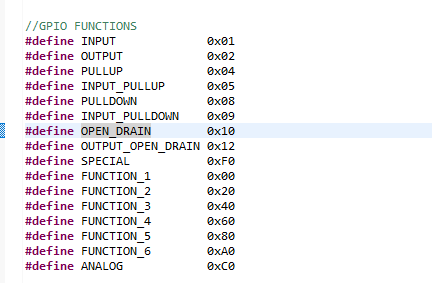
OPEN_DRAIN
Ok. In my case, I’m using Arduino IDE to program the module. Do you have an example on how I can set this GPIO as open drain in Arduino IDE sketch?
pinMode(13, OPEN_DRAIN);
Hi! I have been uing this method of battery measurement over the last year (since V2 has been out). The results were never quite reliable, and I assume, that teh voltage divider circuit was not very precise. But is was sort of good enough for my application.
Now I got a new batch of modules, and there were some apparent changes to the circuit (unfortunately not documented anywhere, it seems). The bad news: the method of voltage measurement that was in the example files does not work anymore… Is there an improved way of measuring battery voltage? Can I get hold of any documentation what the circuit actually looks like right now? ARe there new example files available?
Thsi is rather crucial for me - I am shipping out about a 100 kits every month, and as long as this has not been resolved, I am actually stopped in my tracks, as the software I am using will be broken… 
Any help is appreciated!
Hi:
I’m sorry we didn’t explain the new changes, which caused you trouble.
As you expected, this PCB change is to change the battery detection pin from 13 (ADC2) to 37 (ADC1). This is to avoid the limitation in the ESP32 chip: When WIFI is enabled, ADC2 is occupied by WIFI can not work.
If you need to continue to use the battery test, just change the 13 in the original routine to 37.
Sorry for the trouble, and I apologize again.
Thanks, Saber, this was helpful. BUT: In my application pin 37 is used as GPIO with external pull-up… this means the value read is meaningless. Further consequences: I have to re-design the schematics and PCB and throw away 700 PCBs I had already manufactured. Further problem: I have to maintain two sets of software releases, one for the >1500 items that are already out in the field, and another one for the new version. VERY disappointing.
To come up with a new release that changes pin assignments without notice in advance, and with the same version number, is very unprofessional, to say the least. Not to mention that there still is no up-to-date documentation (schematics) available.
Honestly, I do not know how to proceed from here. Creating a new version with your un-announced changes incorporated seems to be very risky - how long until you change the specs again? I need a supplier I can rely upon.
Hi @oe1wkl
We are very sorry for your problem. Because of the power management bug of ESP32 chip, ADC2 and WiFi cannot work at the same time. So we moved the ADC pins from the original GPIO 13 to GPI 37.
This is a terrible upgrade and we did not update the documentation in a timely manner. Such problems will never happen again in the future.
I think, you can continue to keep pin 37 as a GPIO function by turning off the MOS-FET. Is this okay?
I can use GPIO on Pin37, that’s not the problem - but I cannot at the same time measure the battery voltage, because I have an external pull-up resistor on Pin37, so the voltage is always close to 3.3V (and not around 1.3 through the voltage divider); but I also need the battery measurement in my application.
My question is: can I source around 700 of the older modules from Heltec? I still have 700 PCBs that I do not want to throw into the trash (they were expensive!). The WiFi problem with Pin13 does not disturb me - I only use WiFi for OTA and uploading files, and restart the module, before I measure battery voltage again.
Definitely yes, an agent has feedback your question to my colleague this afternoon.
How long is your time requirement? Production takes about two weeks, but January 20 to February 2 is the Chinese New Year holiday. This is a national holiday, and almost all suppliers and factories will stop working.
OK let’s finalize this via my supplier. We could do this in two batches - 250 before Jan 20, and the rest end of February or early March…
Hi guys,
I tried to find some sample sketch for reading the battery-level, but the only one i found quite helpful is this:
But looking though it, it neither contains “pinMode(13, OPEN_DRAIN);” nor something about GPI 37.
When i uploaded it to my Lora (V2) the battery voltage seems to slowly drop to zero, and the percentage goes to -45% … I guess it tries to read it from A4, so i changed it to analogPin = 37. But then the display stopped working so i changed it back to A4. Now the display works again but the reading doesnt make sense.
Could you please just tell me the few really essential lines i need?
