Thanks, Saber, this was helpful. BUT: In my application pin 37 is used as GPIO with external pull-up… this means the value read is meaningless. Further consequences: I have to re-design the schematics and PCB and throw away 700 PCBs I had already manufactured. Further problem: I have to maintain two sets of software releases, one for the >1500 items that are already out in the field, and another one for the new version. VERY disappointing.
To come up with a new release that changes pin assignments without notice in advance, and with the same version number, is very unprofessional, to say the least. Not to mention that there still is no up-to-date documentation (schematics) available.
Honestly, I do not know how to proceed from here. Creating a new version with your un-announced changes incorporated seems to be very risky - how long until you change the specs again? I need a supplier I can rely upon.
Heltec Wifi LoRa V2 battery management
Hi @oe1wkl
We are very sorry for your problem. Because of the power management bug of ESP32 chip, ADC2 and WiFi cannot work at the same time. So we moved the ADC pins from the original GPIO 13 to GPI 37.
This is a terrible upgrade and we did not update the documentation in a timely manner. Such problems will never happen again in the future.
I think, you can continue to keep pin 37 as a GPIO function by turning off the MOS-FET. Is this okay?
I can use GPIO on Pin37, that’s not the problem - but I cannot at the same time measure the battery voltage, because I have an external pull-up resistor on Pin37, so the voltage is always close to 3.3V (and not around 1.3 through the voltage divider); but I also need the battery measurement in my application.
My question is: can I source around 700 of the older modules from Heltec? I still have 700 PCBs that I do not want to throw into the trash (they were expensive!). The WiFi problem with Pin13 does not disturb me - I only use WiFi for OTA and uploading files, and restart the module, before I measure battery voltage again.
Definitely yes, an agent has feedback your question to my colleague this afternoon.
How long is your time requirement? Production takes about two weeks, but January 20 to February 2 is the Chinese New Year holiday. This is a national holiday, and almost all suppliers and factories will stop working.
OK let’s finalize this via my supplier. We could do this in two batches - 250 before Jan 20, and the rest end of February or early March…
Hi guys,
I tried to find some sample sketch for reading the battery-level, but the only one i found quite helpful is this:
But looking though it, it neither contains “pinMode(13, OPEN_DRAIN);” nor something about GPI 37.
When i uploaded it to my Lora (V2) the battery voltage seems to slowly drop to zero, and the percentage goes to -45% … I guess it tries to read it from A4, so i changed it to analogPin = 37. But then the display stopped working so i changed it back to A4. Now the display works again but the reading doesnt make sense.
Could you please just tell me the few really essential lines i need?

Thanks for answering Saber,
but that doesn’t help me.
Does anyone have a sketch, that reads the battery (connected directly to the board) correctly?
@Saber I have more than 150 wireless stick lite here with me and I order more 150 to my supplier. I would like to now if the power detection pin is still at PIN 13. How can I check this?
Which is the best method to read the battery before the regulator, and after the regulator ?
Hello:
Lite’s battery detection pin is still GPIO13.
I have a WiFi_LoRa_32_V2 (868-915).
With reference to the posts by oe1wkl above about the change from GPIO13 to GPIO37 for battery voltage-divider reads:
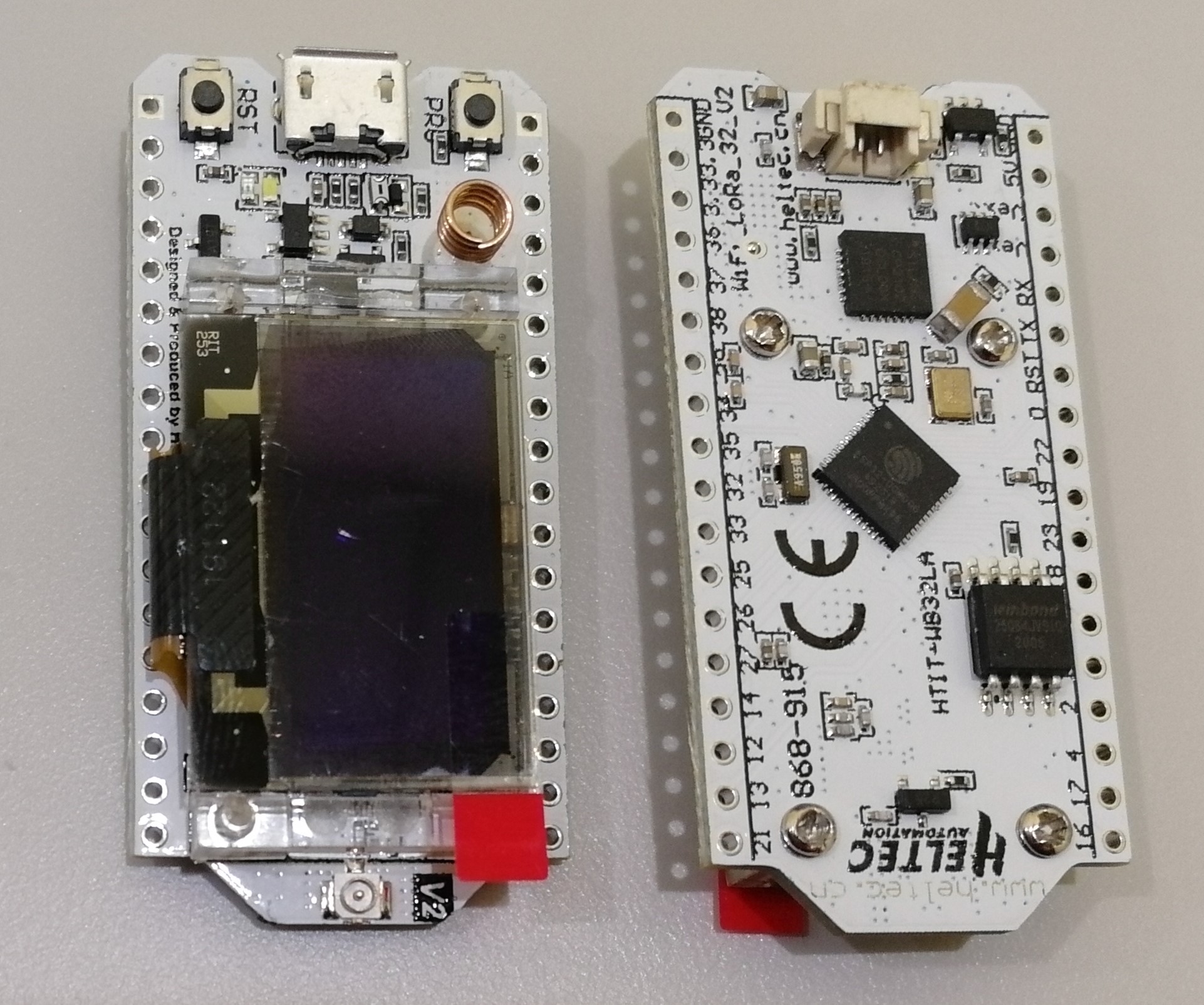
Q. How do we tell what variant of V2 board we have? (i.e. how can I tell which GPIO pin Vbat is connected to)
Given the importance of holding GPIO21 high (to pull the voltage divider to GND and avoid Vbat voltage hitting the ADC ‘undivided’), I want to make sure I know which variant of V2 board I have before I start testing.
Thanks!
I think I just answered this with some DMM (Fluke 289) measurements on my board; for these measurements, I had USB connected together with LiPo (charging), where my Vbat was 4.15V.
- When GPIO21 was HIGH 3.3V, GPIO13 was 0V, GPIO37 was 3.58V, Vext was 2.92V.
- When GPIO21 was LOW 0V, GPIO13 was 0V, GPIO37 was 1.28V, Vext was 3.3V.
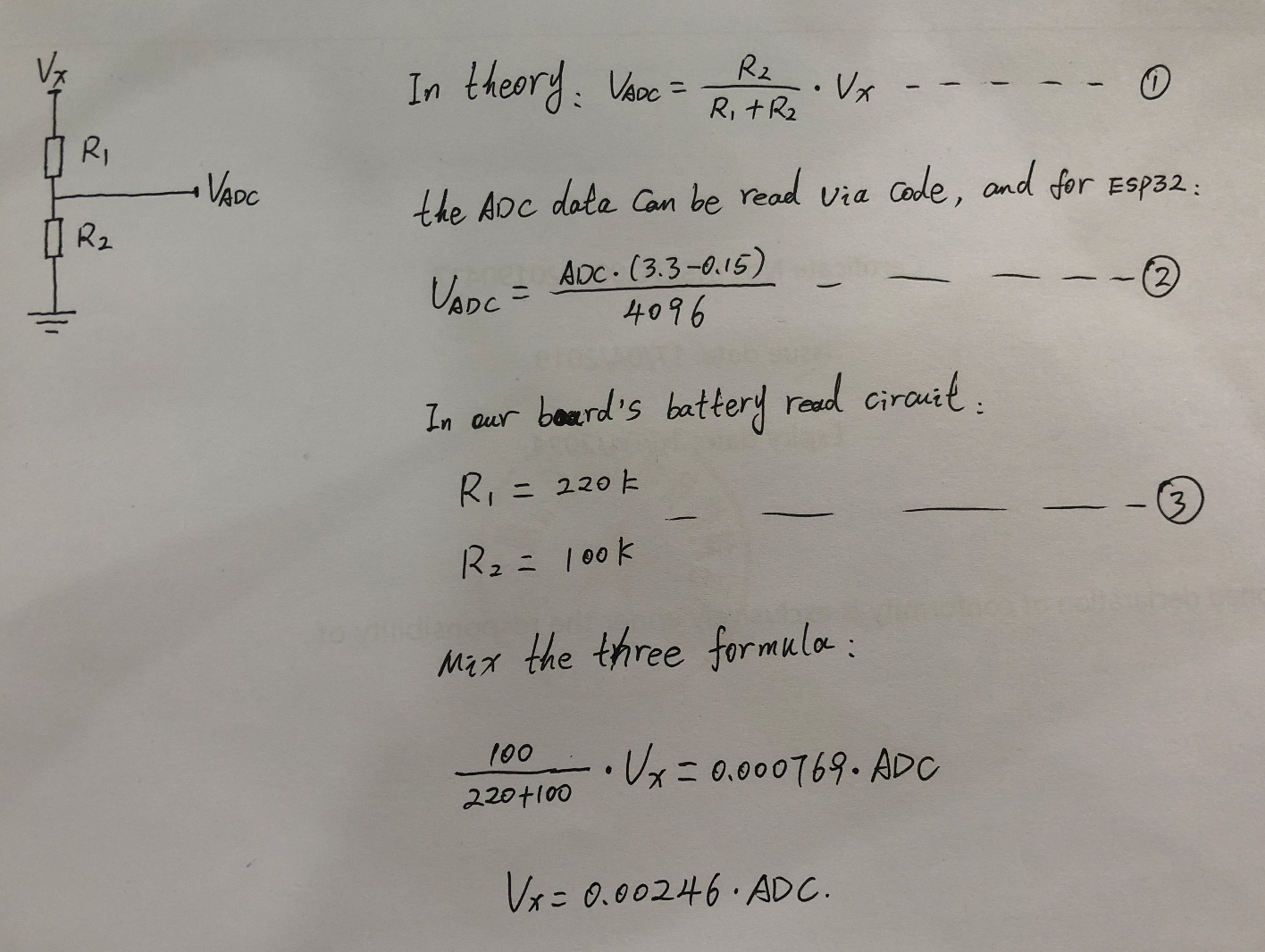
Ignoring the negligible Rds of the AO3401, with the 320K/100K voltage divider, for case (2) I expected approximately 3.2*1.28=4.096V, which was pretty close to my Vbat of 4.15V.
Also, G6EJD has shared a simple ESP32 voltage reading function on github which applies a polynomial correction to the ADC read. Here’s some example output from my test sketch (when my DMM was measuring Vbat of 4.16V:
-> analogRead(37): 1424
-> ReadVoltage(37): 1.30
-> Battery voltage: 4.17Hello,
I’ve been developing sketches for my Heltec Lora V2 and working to try to read the battery voltage. I’ve read a lot here that indicates that the internal divider provided (activated by GPIO21 = LOW) tied to originally GPIO13/ADC2_4 and has moved to GPIO37/ADC1_1. I don’t seem to be getting any good values out of mine over about 1.2v (before x3.2 divider). That is on a 6dB gain. I think that means I need to move to a higher gain, even with the divider, but the range for 6dB atten setting says that should go from 150mV-1750mV… I really think I need to know how to determine WHICH version of V2 I have (old GPIO13 vs. new 37)? GPIO13 seems to be at or near 100mV for both states of GPIO21. But I really am struggling with why I can’t get readings that never seem to differ from 1.21v (even with a very low lipo around 3.2v or up to 4.2v).
BTW, I think I have found the V2.1 documentation and revision history, however, they both show V2 on board, so no way that I can see to determine difference, other than compare voltage on GPIO37 vs 13, I think.
https://heltec-automation-docs.readthedocs.io/en/latest/esp32/wifi_lora_32/hardware_update_log.html#v2-1
Somehow, I seem to have things working with the 6dB atten now and I’m using the EFuse compensated internal calibration readings as well for ADC1. I am not certain what was being done incorrectly before (possibly something I had in the ADC setup was setting me at 0dB atten through the various sketches I was trying to copy ADC readings from). I’ll try to clean up what I have working to just demo what I’ve got working and upload sketch.
Also, the V2.1 pinout document is wrong:
It shows labeled 3v3 and GND in upper left (3rd/4th pin from top left), where those are BOTH actually clearly labeled Vext on the board silkscreen on back and I’ve confirmed are = 3.3v when GPIO21 low (see the image below for the silkscreen label that shows it also Vext and Vext):
Here is a sample sketch that will setup the ADC reads (with per board EFuse calibration conversion/compensation), ensures some settle time for GPIO pins to ADC, adds in a sample / averaging buffer, has low voltage cutoff to deep sleep, uses light sleep if on battery mode at some threshold, and works with both V2.0 and V2.1 boards.
Note: I’m not sure why I can’t set GPIO21 LOW in setup and never digital write it low again, but have to continually assert it low in the ADC reading routines (this must have been my original issue with floating values and why I couldn’t get things functioning well…once I put the GPIO21 drive low in the loop at each ADC scan, it works). Something in my routines is turning off GPIO21 or something in the OLED drivers is…
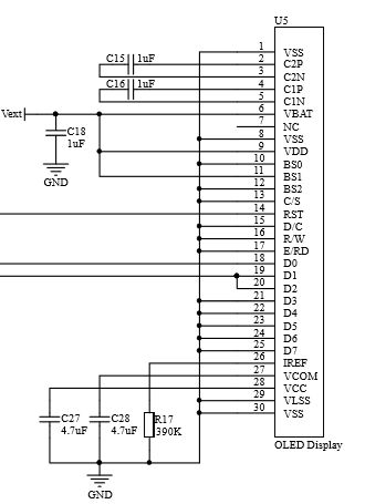
Originally, I tried to set this up to just pulse the GPIO21 low and connect the ADC read during the scan and then turn GPIO21 back off, but it appears the OLED display is now powered off of Vext since V2.0 and flipping GPIO21 high disconnects Vext from 3.3v now. The OLED seems to still work, just lower brightness, which I can only assume is because the display is powering from forward biasing input clamps from I2C SCL/SDA when writing…anyway…pretty obvious from the V2.0 schematic, you shouldn’t raise GPIO21 high if you want to use OLED…
// Heltec WiFi LoRa V2 battery read example
// by Jeff McClain  jeff@themcclains.net
//
#include <Arduino.h>
#include <esp_adc_cal.h>
#include <driver/adc.h>
#include "heltec.h"

#define MAXBATT                 4200    // The default Lipo is 4200mv when the battery is fully charged.
#define LIGHT_SLEEP_VOLTAGE     3750    // Point where start light sleep
#define MINBATT                 3200    // The default Lipo is 3200mv when the battery is empty...this WILL be low on the 3.3v rail specs!!!

#define VOLTAGE_DIVIDER         3.20    // Lora has 220k/100k voltage divider so need to reverse that reduction via (220k+100k)/100k on vbat GPIO37 or ADC1_1 (early revs were GPIO13 or ADC2_4 but do NOT use with WiFi.begin())
#define DEFAULT_VREF            1100    // Default VREF use if no e-fuse calibration
#define VBATT_SAMPLE            500     // Battery sample rate in ms
#define VBATT_SMOOTH            50      // Number of averages in sample
#define ADC_READ_STABILIZE      5       // in ms (delay from GPIO control and ADC connections times)
#define LO_BATT_SLEEP_TIME      10*60*1000*1000     // How long when low batt to stay in sleep (us)
#define HELTEC_V2_1             1       // Set this to switch between GPIO13(V2.0) and GPIO37(V2.1) for VBatt ADC.
#define VBATT_GPIO              21      // Heltec GPIO to toggle VBatt read connection ... WARNING!!! This also connects VEXT to VCC=3.3v so be careful what is on header.  Also, take care NOT to have ADC read connection in OPEN DRAIN when GPIO goes HIGH
#define __DEBUG                 0       // DEBUG Serial output

uint16_t Sample();
void drawBattery(uint16_t, bool = false);

esp_adc_cal_characteristics_t *adc_chars;


void setup() {
  while (! Serial);
  delay(20);

  // Characterize ADC at particular atten
  #if (defined(HELTEC_V2_1))
  adc_chars = (esp_adc_cal_characteristics_t*)calloc(1, sizeof(esp_adc_cal_characteristics_t));
  esp_adc_cal_value_t val_type = esp_adc_cal_characterize(ADC_UNIT_1, ADC_ATTEN_DB_6, ADC_WIDTH_BIT_12, DEFAULT_VREF, adc_chars);
  adc1_config_width(ADC_WIDTH_BIT_12);
  adc1_config_channel_atten(ADC1_CHANNEL_1,ADC_ATTEN_DB_6);
  #else
  // Use this for older V2.0 with VBatt reading wired to GPIO13
  adc_chars = (esp_adc_cal_characteristics_t*)calloc(1, sizeof(esp_adc_cal_characteristics_t));
  esp_adc_cal_value_t val_type = esp_adc_cal_characterize(ADC_UNIT_2, ADC_ATTEN_DB_6, ADC_WIDTH_BIT_12, DEFAULT_VREF, adc_chars);
  adc2_config_channel_atten(ADC2_CHANNEL_4,ADC_ATTEN_DB_6);
  #endif

  #if defined(__DEBUG) && __DEBUG > 0
  Serial.printf("ADC Calibration: ");
  if (val_type == ESP_ADC_CAL_VAL_EFUSE_VREF) {
      Serial.printf("eFuse Vref\n");
  } else if (val_type == ESP_ADC_CAL_VAL_EFUSE_TP) {
      Serial.printf("Two Point\n");
  } else {
      Serial.printf("Default[%dmV]\n",DEFAULT_VREF);
  }
  #else
  if (val_type);    // Suppress warning
  #endif

  Heltec.begin(true /*DisplayEnable Enable*/, false /*LoRa Disable*/, true /*Serial Enable*/);
  Heltec.display->flipScreenVertically();
  Heltec.display->setFont(ArialMT_Plain_10);
  Heltec.display->clear();

  #if defined(__DEBUG) && __DEBUG >= 1
  Serial.printf("ADC Calibration: ");
  if (val_type == ESP_ADC_CAL_VAL_EFUSE_VREF) {
      Serial.printf("eFuse Vref\n");
  } else if (val_type == ESP_ADC_CAL_VAL_EFUSE_TP) {
      Serial.printf("Two Point\n");
  } else {
      Serial.printf("Default[%dmV]\n",DEFAULT_VREF);
  }
  #else
  if (val_type);    // Suppress warning
  #endif

  // Prime the Sample register
  for (uint8_t i = 0;i < VBATT_SMOOTH;i++) {
    Sample();
  }

  pinMode(VBATT_GPIO,OUTPUT);
  digitalWrite(VBATT_GPIO, LOW);              // ESP32 Lora v2.1 reads on GPIO37 when GPIO21 is low
  delay(ADC_READ_STABILIZE);                  // let GPIO stabilize

}


void loop() {
  Heltec.display->clear();
  uint16_t voltage = Sample();
  drawBattery(voltage, voltage < LIGHT_SLEEP_VOLTAGE);
  Heltec.display->display();

  if (voltage < MINBATT) {                  // Low Voltage cut off shut down to protect battery as long as possible
    Heltec.display->setColor(WHITE);
    Heltec.display->setFont(ArialMT_Plain_10);
    Heltec.display->setTextAlignment(TEXT_ALIGN_CENTER);
    Heltec.display->drawString(64,24,"Shutdown!!");
    Heltec.display->display();
    delay(2000);
    #if defined(__DEBUG) && __DEBUG > 0
    Serial.printf(" !! Shutting down...low battery volotage: %dmV.\n",voltage);
    delay(10);
    #endif
    esp_sleep_enable_timer_wakeup(LO_BATT_SLEEP_TIME);
    esp_deep_sleep_start();
  } else if (voltage < LIGHT_SLEEP_VOLTAGE) {     // Use light sleep once on battery
    uint64_t s = VBATT_SAMPLE;
    #if defined(__DEBUG) && __DEBUG > 0
    Serial.printf(" - Light Sleep (%dms)...battery volotage: %dmV.\n",(int)s,voltage);
    delay(20);
    #endif
    esp_sleep_enable_timer_wakeup(s*1000);     // Light Sleep does not flush buffer
    esp_light_sleep_start();
  }
  delay(ADC_READ_STABILIZE);
}


// Poll the proper ADC for VBatt on Heltec Lora 32 with GPIO21 toggled
uint16_t ReadVBatt() {
  uint16_t reading = 666;

  digitalWrite(VBATT_GPIO, LOW);              // ESP32 Lora v2.1 reads on GPIO37 when GPIO21 is low
  delay(ADC_READ_STABILIZE);                  // let GPIO stabilize
  #if (defined(HELTEC_V2_1))
  pinMode(ADC1_CHANNEL_1, OPEN_DRAIN);        // ADC GPIO37
  reading = adc1_get_raw(ADC1_CHANNEL_1);
  pinMode(ADC1_CHANNEL_1, INPUT);             // Disconnect ADC before GPIO goes back high so we protect ADC from direct connect to VBATT (i.e. no divider)
  #else
  pinMode(ADC2_CHANNEL_4, OPEN_DRAIN);        // ADC GPIO13
  adc2_get_raw(ADC2_CHANNEL_4,ADC_WIDTH_BIT_12,&reading);
  pinMode(ADC2_CHANNEL_4, INPUT);             // Disconnect ADC before GPIO goes back high so we protect ADC from direct connect to VBATT (i.e. no divider
  #endif

  uint16_t voltage = esp_adc_cal_raw_to_voltage(reading, adc_chars);
  voltage*=VOLTAGE_DIVIDER;

  return voltage;
}

//  Use a buffer to average/sample ADC
uint16_t Sample() {
  static uint8_t i = 0;
  static uint16_t samp[VBATT_SMOOTH];
  static int32_t t = 0;
  static bool f = true;
  if(f){ for(uint8_t c=0;c<VBATT_SMOOTH;c++){ samp[c]=0; } f=false; }   // Initialize the sample array first time
  t -= samp[i];   // doing a rolling recording, so remove the old rolled around value out of total and get ready to put new one in.
  if (t<0) {t = 0;}

  // ADC read
  uint16_t voltage = ReadVBatt();

  samp[i]=voltage;
  #if defined(__DEBUG) && __DEBUG > 0
  Serial.printf("ADC Raw Reading[%d]: %d", i, voltage);
  #endif
  t += samp[i];

  if(++i >= VBATT_SMOOTH) {i=0;}
  uint16_t s = round(((float)t / (float)VBATT_SMOOTH));
  #if defined(__DEBUG) && __DEBUG > 0
  Serial.printf("   Smoothed of %d/%d = %d\n",t,VBATT_SMOOTH,s);
  #endif

  return s;
}


void drawBattery(uint16_t voltage, bool sleep) {
  Heltec.display->setColor(BLACK);
  Heltec.display->fillRect(99,0,29,24);

  Heltec.display->setColor(WHITE);
  Heltec.display->drawRect(104,0,12,6);
  Heltec.display->fillRect(116,2,1,2);

  uint16_t v = voltage;
  if (v < MINBATT) {v = MINBATT;}
  if (v > MAXBATT) {v = MAXBATT;}
  double pct = map(v,MINBATT,MAXBATT,0,100);
  uint8_t bars = round(pct / 10.0);
  Heltec.display->fillRect(105,1,bars,4);
  Heltec.display->setFont(ArialMT_Plain_10);
  Heltec.display->setTextAlignment(TEXT_ALIGN_RIGHT);
  // Draw small "z" when using sleep
  if (sleep > 0) {
    Heltec.display->drawHorizontalLine(121,0,4);
    Heltec.display->drawHorizontalLine(121,5,4);
    Heltec.display->setPixel(124,1);
    Heltec.display->setPixel(123,2);
    Heltec.display->setPixel(122,3);
    Heltec.display->setPixel(121,4);
  }
  Heltec.display->drawString(127,5,String((int)round(pct))+"%");
  Heltec.display->drawString(127,14,String(round(voltage/10.0)/100.0)+"V");
  #if defined(__DEBUG) && __DEBUG > 0
  static uint8_t c = 0;
  if ((c++ % 10) == 0) {
    c = 1;
    Serial.printf("VBAT: %dmV [%4.1f%%] %d bars\n", voltage, pct, bars);
  }
  #endif
}Hi there.
I’m still having difficulties to read battery voltage. I’ve configured GPIOs and ADC attenuation like following:
#define GPIO_HABILITA_LEITURA_BATERIA 21
#define GPIO_ADC_BATERIA 13
#define BITS_RESOLUCAO_ADC 12 //max: 4095
#define MAX_VALOR_ADC_BAT 4095
void configura_leitura_tensao_bateria(void)
{
/* Configura GPIO do ADC inicialmente como open drain para evitar que
o habilitar da leitura de tensão de bateria envie diretamente 4.7V (max)
ao ADC */
pinMode(GPIO_ADC_BATERIA, OPEN_DRAIN);
/* Configura ADC */
analogSetPinAttenuation(GPIO_ADC_BATERIA, ADC_6db);
analogReadResolution(BITS_RESOLUCAO_ADC);

/* Habilita leitura da tensão de bateria */
pinMode(GPIO_HABILITA_LEITURA_BATERIA, OUTPUT);
digitalWrite(GPIO_HABILITA_LEITURA_BATERIA, LOW);
}
And I’m trying to read as follows:
bat_analog_read = analogRead(GPIO_ADC_BATERIA);
Serial.print("Analog read (battery): ");
Serial.println(bat_analog_read);
However, I’ve got very inconsistent readings:
ead (battery): 256
Analog read (battery): 502
Analog read (battery): 721
Analog read (battery): 448
Analog read (battery): 64
Analog read (battery): 6
Analog read (battery): 86
Analog read (battery): 256
Analog read (battery): 491
Analog read (battery): 709
Analog read (battery): 416
Analog read (battery): 49
Analog read (battery): 6
If I switch to GPIO 37 (as used in board V2.1), I only get 0 as readings.
Please, would you tell me what I’m doing wrong? I have no idea what’s wrong with my approach.
Cool!!!
I will try you code tomorrow!
Hi Bro… You avatar blink blinded my eye 
When my son was born, a relative photoshopped my face onto his body and said “He looks just like you!” LoL.